UHV High-Neck Flange Welding
On this page
During the production of steel pipe towers for UHV transmission lines, the welding of steel pipes to high-neck flanges is critical to the quality and progress of the entire project. Therefore, when dealing with large production volumes and a compressed construction schedule, the company must select a reasonable, efficient, and high-quality structural design and welding process to meet project demands. Comparatively, high-neck butt-weld flanges are better suited to meet these requirements. The connection between high-neck butt-weld flanges and circumferentially butted steel pipes involves only one circumferential butt welding seam. Previously, this type of joint was used exclusively in critical pipe connections, such as high-temperature and high-pressure steam pipelines in power plants and high-pressure pipes in petrochemical applications. It has only been applied to steel pipe towers in power transmission and transformation lines in recent years. The advantages of this joint design include a simple structure, equal strength, rapid welding speed, absence of ribs, ease of welding seam inspection, and reduced welding material consumption.
The requirements for welding technology are high, and the equal strength of the welding seam can only be ensured with full penetration. Ensuring the stability of welding seam quality is a significant challenge. The formulation of the welding process and the selection of welding materials directly affect welding seam quality and welding speed. In addition, the groove angle, blunt edge, butt gap, and roundness deviation also affect welding seam penetration.
The requirements for welding technology are high, and the equal strength of the welding seam can only be ensured with full penetration. Ensuring the stability of welding seam quality is a significant challenge. The formulation of the welding process and the selection of welding materials directly affect welding seam quality and welding speed. In addition, the groove angle, blunt edge, butt gap, and roundness deviation also affect welding seam penetration.
Two main methods are used for circumferential welding of UHV high-neck butt-welded flanges and steel pipes: manual gas-shielded welding and fully automatic swing gas-shielded welding. Building on these two welding methods, some UHV steel pipe tower manufacturers have developed internal and external submerged arc circumferential welding machines to achieve circumferential welding of high-neck butt-welded flanges and steel pipes, considering the welding process characteristics, production process, component shape, and other factors. This process uses submerged arc welding to perform double-sided penetration welding on the workpiece, eliminating the need for root cleaning and maximizing welding efficiency while ensuring high quality. Currently, double-sided submerged arc welding can be achieved with a minimum diameter of approximately 300 mm. With the ongoing production of high-neck butt-welded flanges, welding methods and technologies are continually improving. Based on the specifications and dimensions of the workpiece, manual gas-shielded welding, fully automatic swing gas-shielded welding, submerged arc welding, or other suitable welding methods can be selected.
(1) The bevel opening of the high-neck flange on the UHV steel pipe tower and the steel pipe should follow the specified welding process requirements. A sufficient welding seam gap must be reserved to ensure full penetration of the butt welding seam, and an appropriate blunt edge should be provided to prevent root burn-through. For gas-shielded welding, a gap of 0–2 mm and a blunt edge of 0–2 mm can be reserved. For submerged arc welding, a gap of 0–1 mm should be reserved, and the blunt edge should be ≥7 mm.
(2) The bevel processing diagrams are shown in Figures 3 to 6.
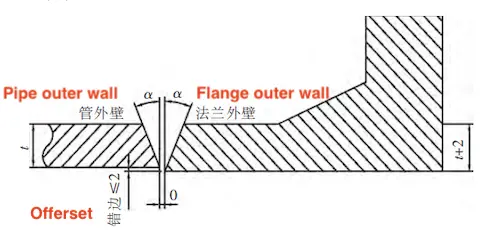
Figure 3 Thin wall Y-shaped groove
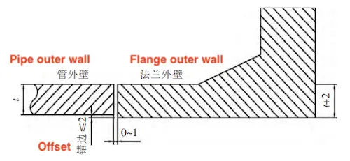
Figure 4 I-shaped groove
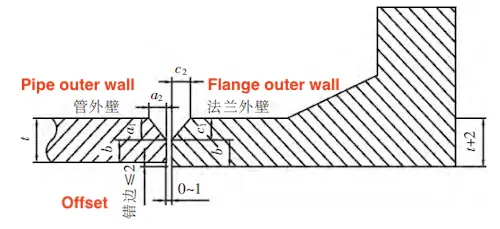
Figure 5 Y-shaped groove a
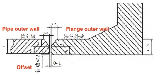
Figure 6 Y-shaped groove b
(2) The bevel processing diagrams are shown in Figures 3 to 6.

Figure 3 Thin wall Y-shaped groove

Figure 4 I-shaped groove

Figure 5 Y-shaped groove a

Figure 6 Y-shaped groove b
The selection of welding materials should ensure that the strength, toughness, and plasticity of the welding rod match the various properties of the parent material. The UHV flange is generally made from Q345B steel, and ER50-X welding wire is typically used for gas shielded welding (GMAW) . If special steels and welding methods are used, they must be implemented in accordance with GB 50661-2011.
Before commencing welding operations, the manufacturing unit should conduct a welding process assessment in accordance with the relevant requirements of GB 50661-2011 and DI/T 868-2004, and prepare welding process regulations.
The circumferential butt weld between the UHV long-neck flange and the steel pipe must meet the requirements for a first-class welding seam.
(1) Positioning welding must be performed by welders who hold the corresponding qualification certificates.
(2) The surface and both sides of the parent material near the positioning welding seam should be uniform and smooth and free of burrs, cracks, oxide scale, rust, grease, water, and other impurities.
(3) The thickness of the positioning welding seam should not be less than 3 mm and should not exceed 2/3 of the designed welding seam height. The length should not be less than 40 mm, and the spacing should be between 200 mm and 300 mm. The positioning welding seam should generally consist of no fewer than three points and should be evenly distributed.
(1) The wind speed during gas shielded welding should not exceed 2 m/s.
(2) The relative humidity of the air should not exceed 80%.
(3) The surface of the weldment must be kept dry.
(4) The welding environment should ideally be at room temperature, with a minimum of 0°C.
(2) The relative humidity of the air should not exceed 80%.
(3) The surface of the weldment must be kept dry.
(4) The welding environment should ideally be at room temperature, with a minimum of 0°C.
(1) The preheating temperature and interpass temperature should be determined based on comprehensive factors such as the chemical composition of the steel, the restraint state of the joint, the heat input, the hydrogen content level of the deposited metal, and the welding method used.
(2) The minimum interpass temperature during welding must be equal to or greater than the preheating temperature, and the maximum interpass temperature must not exceed 230°C.
(2) The minimum interpass temperature during welding must be equal to or greater than the preheating temperature, and the maximum interpass temperature must not exceed 230°C.
The difference between the maximum welding seam width (Bmax) and the minimum welding seam width (Bmin) shall not exceed 4.0 mm within any 50 mm of welding seam length, and the total deviation shall not exceed 5.0 mm for the entire welding seam length. The welding seam width must comply with the provisions outlined in Table 2, and the welding seam diagram is illustrated in Figures 7 and 8.
Table 2 welding seam width
Table 2 welding seam width
| Welding Method | Weld Form | Welding Seam Width (B/mm) | |
| Bmin | Bmax | ||
| Submerged Arc Welding | I-shaped Welding Seam | b + 6 | b + 16 |
| Non-I-shaped Welding Seam | g + 4 | g + 14 | |
| Gas Shielded Welding | I-shaped Welding Seam | b + 4 | b + 8 |
| Non-I-shaped Welding Seam | g + 4 | g + 8 | |
Please note that 6 in the table refers to the assembly gap, which should comply with the actual assembly values required by the GB/T 985.1-2008 and GB/T 985.2-2008 standards. Additionally, g represents the groove surface width.
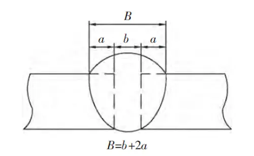
Figure 7 I-groove butt welding seam
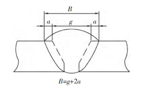
Figure 8 Non-I-shaped groove butt welding seam
(1) Steel pipe tower manufacturers should formulate welding process regulations that meet the requirements of the quality system.
(2) Before welding, steel pipe tower manufacturers should conduct a welding process assessment in accordance with the relevant requirements of JGJ 81-2002, and the welding process assessment report should be filed for reference. At the same time, the welding process instructions and welding process cards for specific products should be compiled in conjunction with product characteristics and production conditions. The welding process card should include at least the following:
① Preparation basis and product or component name
② Welder qualification requirements and environmental requirements
③ Welding methods
④ Steel, welding materials, and auxiliary materials
⑤ Groove preparation requirements, dimensions, and allowable deviations
⑥ Weld bead design, tack welding, and welding sequence requirements
⑦ Welding current, arc voltage, welding speed, and root cleaning requirements for each weld bead
The appearance of the welding seam should not exhibit root incompleteness, incomplete welding, root shrinkage, undercut, cracks, arc pit cracks, arc scratches, spatter, poor joints, surface slag inclusions, gas holes, weld nodules, etc. The welding appearance should be uniform in shape, well-formed, with smooth transitions between welds and between welds and base metal.
The circumferential welding seam of the UHV long-neck flange shall undergo 100% inspection in accordance with the standards for first-level welds. The corresponding ultrasonic flaw detection methods shall be adopted according to the different pipe diameters and thicknesses:
(1) For components with a pipe diameter greater than 356 mm and a thickness greater than 8 mm, single-side double-sided ultrasonic flaw detection shall be conducted on the steel pipe side using an oblique probe with a K value of 2.5.
(2) For steel pipe components with a thickness of 8 mm or less, creeping wave flaw detection shall be conducted on the outer side of the pipe wall using a creeping wave flaw detection probe.
(3) For components with a pipe diameter of 356 mm or less and a wall thickness greater than 8 mm, two or more K value oblique probes shall be used to perform single-side flaw detection on the outer wall of the steel pipe.
The testing services shall be responsible for the quality of welding seams, ensuring that the quality of welded joints with a wall thickness of ≤8 mm meets the allowable values specified in "Ultrasonic Inspection and Quality Assessment of Thin-Walled Butt Welding seams of Steel Pipe Towers for Ultra-High Voltage Transmission Lines." Additionally, the quality of welded joints with a wall thickness greater than 8 mm must meet Inspection Level B and Assessment Level I of GB/T 11345-2013, titled "Manual Ultrasonic Flaw Detection Methods and Flaw Detection Result Classification of Steel Welding seams."
Currently, the production technology for high-neck forged flanges has gradually matured, demonstrating good overall quality, with the first-time pass rate of welding seams reaching 98%. All key qualities meet the technical requirements for steel pipe tower production; however, the process needs further solidification.
Related News
- Installation of Main Bolts for Lap Joint Flange in High-Temperature Gas-Cooled Reactors
- Structural Design and Finite Element Analysis of Anchor Flanges
- Key Welding Technology for High-Neck Flange and Steel Pipe Joints
- The Design and Calculation of Stamped Lap Joint Flanges
- Development of Manufacturing Large Anchor Flanges
- Hardfacing the Inner Surface of Long-Neck Flanges Using CO₂ Gas-Shielded Welding
- UHV High-Neck Flange Welding
- Application of High-Neck Flange to UHV Steel Pipe Tower
- Analysis of the Cracking Cause of High-Neck Flanges
- Anchor Flanges for the East-West Gas Transmission Project
