The Leakage between Valve Bodies and Socket Welded Flanges
Abstract: the microscopic morphology of the cracked fracture, corrosion products and metallographic structure of the joint between the valve body and the socket welded flange were introduced in this article. The causes of failures, such as the incomplete penetration of the welding seam between the valve body and the socket welded flange, and the fatigue cracking of the welding seam caused by the valve under vibration were analyzed, and solutions were proposed.
1. Overview
The system working condition of the buffer tank at the inlet of the circulating hydrogen compressor is that the operating pressure is 11MPa, temperature 40 to 50°C, and medium H2. The content of H2S is 0.04% to 0.05%. A socket welded flanged gate valve of 1 inch and Class 900 is used on buffer tank gauges. The valve conforms to ASME B31. 3 standard; the valve body is made from carbon steel, and the wall thickness is less than 20mm; the welding seam of the socket welded flange does not need post-welding heat treatment. After the valve has been in operation for one year, leakage occurs at the welding seam between the valve body and the socket welded flange. Aiming at this phenomenon, the analysis of the failure is carried out from various aspects and effective suggestions and measures are put forward.
2. Analysis
(1) Selecting materials
After chemical composition analysis, it is determined that low-carbon steel is selected for the valve, which corresponds to the steel grade. The material is No. 20 steel, and the specific chemical analysis results are shown in Table 1.
Table 1 Chemical Composition of Socket Welded Valves %
| C | Mn | Si | S | P | Cr | Ni | Cu | |
| Base metal | 0.22 | 0.58 | 0.28 | 0.014 | 0.007 | 0.06 | 0.06 | 0.22 |
| Welding seams | 0.13 | 1.12 | 0.63 | 0.016 | 0.010 | Less than 0.03 | 0.04 | 0.22 |
(2) Macroscopic morphology and metallographic structure
The dyeing penetrant inspection was carried out on the socket welding seam of the valve body and the flange near the leakage point, and it was found that there was a crack on the center line of the welding seam, which was also the position of the arc of the welding seam. Sampling at the cracked weld, it can be observed that the welding seam has incomplete penetration, and the incomplete penetration of the welding seam, heat-affected zone and root can be determined on the metallographic sample (Figure 1). Radial stripes and arc stripes perpendicular to the direction of crack propagation can be seen from the crack morphology. The fracture surface is relatively smooth, and the fractures fit together very well. Analysis and research prove that the crack belongs to fatigue crack growth; it is preliminarily determined that the crack is a fatigue crack, and the crack source is at the root of the welding seam.
Since the welding has not undergone post-weld heat treatment, it is also necessary to analyze whether the structure of the welding seam and the base metal has an impact on the generation of cracks from the metallographic structure of the material. The boundary between the welding seam and the base metal can be seen in Figure 1. Through metallographic analysis, the microstructure of the base metal and heat-affected zone is ferrite and pearlite; the microstructure of the heat-affected zone is Widmanstatten structure, and the welding seam microstructure is composed of reticulated ferrite, pearlite and upper bainite. There are also arc-shaped inclusions in the heat-affected zone (polished state), but these inclusions should not affect on the crack growth and fracture. The grains of the base metal are relatively fine, which is affected by the cooling rate after welding, and no post-weld heat treatment has been performed.
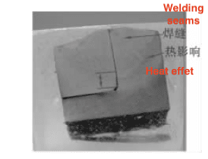
Figure 1 The metallographic sample
(3) Microscopic morphology and corrosion products of crack fracture
After the crack fracture was opened, its microscopic features were observed under the scanning electron microscope (Figures 2 and 3).
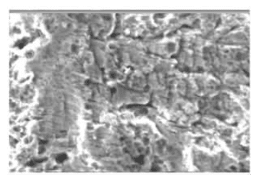
Figure 2 Microscopic morphology of the crack fracture
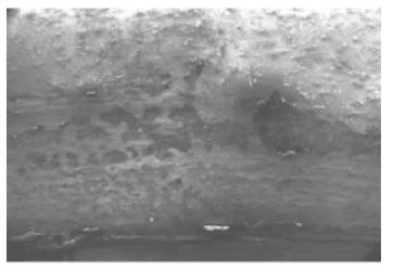
Figure 3 Microscopic morphology of the crack fracture
It can be seen from the microscopic fracture morphology that corrosion products and fatigue striations are attached to the fatigue fracture, and the necessary condition for fatigue striations is that the crack tip is under an open plane strain state. According to this, it is judged that the fracture should belong to the high-stress low cycle fatigue fracture.
At the same time, the energy spectrum analysis was carried out on the corrosion product elements existing in the fracture, and the S content was high, which was caused by the medium entering the fracture through the crack gap. The contents of other chemical elements are normal. Therefore, the causes of crack propagation and leakage should also include damage caused by stress corrosion and corrosion fatigue.
(4) Working conditions
The valve is installed on the liquid level gauge and is in a cantilever state. Under the action of self-gravity, this part is subjected to great tensile stress, and the crack is located in the upper part of the welding seam of the valve. Through the finite element simulation calculation, the stress distribution states in the two cases, namely non-penetration and penetration are obtained (Figures 4 and 5). It can be seen from the calculation model that when the socket welding seam of the valve body and the flange is not penetrated, the stress concentration at the root is concentrated. At the same time, the valve is on the buffer tank where the inlet of the circulating hydrogen compressor is under vibration, thus forming fatigue cracks and great strain for crack growth. If the welding seam is performed well, the stress level at the root of the welding seam is low. At the same time, the welding seam has not undergone heat treatment, and there is also a great residual stress. The residual stress is great, especially at the end of the arc of the welding seam. The toughness and plasticity of the material decrease, resulting in a decrease in the fatigue limit, and the fatigue crack expands at the end of the welding seam.
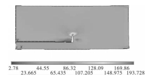
Figure 4 The state of stress concentration when the welding is not performed well.
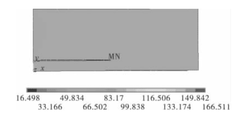
Figure 5 Stress evenly distributed in the welding head
3. Conclusion
The main reason for the leakage failure of the socket welding seam of the valve body and flange is that the socket welding seam is not penetrated; there is stress concentration, fatigue cracks are generated during operation, and the cracks are expanded under vibration. For similar valves in operation, certain measures should be taken to detect socket welded seams and replace valves with incomplete welding or similar working conditions. When choosing a flanged valve, it is recommended to use a butt welded flange structure, and non-destructive testing should be carried out after welding to avoid harmful defects in the valve material.
Related News
- Failure and Crack Analysis of an EO/EG Unit Tower Inlet Flange
- Pipe Flange Bolt Tightening in LNG Projects: Key Considerations
- Ultrasonic Testing of High-Neck Flange Welds
- Underwater Flange Connection Methods for Submarine Pipelines
- Key Technologies for Pressure Vessel Testing and Flange Connection Design
- Installation of Main Bolts for Lap Joint Flange in High-Temperature Gas-Cooled Reactors
- Structural Design and Finite Element Analysis of Anchor Flanges
- Key Welding Technology for High-Neck Flange and Steel Pipe Joints
- The Design and Calculation of Stamped Lap Joint Flanges
- Development of Manufacturing Large Anchor Flanges
