The Design and Calculation of Stamped Lap Joint Flanges
This study introduces the steel stamped lap joint flange, a novel non-standard pipe flange, and examines the feasibility of applying the widely used Waters for its design and calculation. The analysis provides an outlook on the theoretical calculations for these flanges. Major manufacturers of stamped lap joint flanges in Europe and the United States include KREMO (Germany), BENE INOX (France), and MARYLAND METRICS (USA), which follow the DIN 2642 and DIN 2576 production standards. Globally, stamped flanges are predominantly used in dyeing machines, with TC (Germany) being an early adopter.
In China, several dyeing machine manufacturers have proposed adopting stamped flanges, but the lack of a design foundation for this non-standard flange—since GB150 relies on flat plate theory—has delayed approval. Flange design and calculation have evolved over more than a century, from the Bach method introduced in Germany in 1891 to the EN 1591 standard established in 2009. These methods can be categorized into three historical stages: material mechanics-based, elastic analysis-based, and plastic limit-based analysis. The Waters method, which is based on elastic analysis, remains the most widely used design approach. It has influenced the development of flange design standards such as ASME (USA), GB150 (China), BS (UK), JIS (Japan), and CODAP (France).
Since its introduction by Taylor and Waters in 1937, the Waters method has undergone extensive refinement by researchers. Waters defined "flange design" as comprising three components: gasket design, bolt design, and flange design, emphasizing that failure in any of these could directly impact the other components and lead to different results.
The Waters method is a non-standard approach to flange design and calculation, based on the theory of linear elastic plates and shells. Flanges are classified as either integral (including necked) or loose (including necked), depending on the rigidity of the connection between the flange ring and the cylinder or cone neck. "Arbitrary flanges" typically fall between these two categories. The stress calculation formula for integral flanges is also applicable to loose and necked loose flanges, with the coefficients FFF and VVV adjusted accordingly for loose flanges.
The core principle of the Waters method is to calculate the maximum flange stress using elastic analysis, factoring in the gasket coefficient (mmm) and sealing pressure (yyy). By determining the flange force and controlling its dimensions, the method ensures that the connection meets sealing requirements.
The foundational assumptions for deriving the Waters method are as follows:
- The flange remains elastic at the design temperature, with no creep or plastic deformation, ensuring all stress and strain stay within the elastic range.
- The bolt load (WWW), gasket load (HGH), and hydrostatic axial forces (HD and Hr) are predefined.
- The bolt load and lever arm are treated as fixed values, with their product representing the external torque applied to the flange. This torque acts as an equivalent couple on the flange ring’s inner and outer diameters.
- The shell and cone neck are modeled as middle surfaces aligned with their inner surfaces. At the connection to the ring plate’s middle surface, the radial displacement at the large end of the cone neck is assumed to be zero due to displacement continuity.
- Flange ring deflection and deformation are negligible, as are the radial displacement of the annular centroid and the elongation of the neutral surface caused by bending.
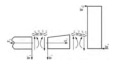
Based on the simplifications and assumptions made by Waters, the resulting calculation model is shown in Figure 1.

Figure 1 Flange Force Diagram
Waters divides the flange—whether a flat-welding flange or a long-neck butt-welding flange—into three components for stress analysis: the shell, the cone neck, and the flange ring.
- Shell Stress Analysis: The shell is modeled as a semi-infinite cylindrical shell subjected to a uniformly distributed bending moment (M) and shear force (Q₀) at the edge, where X₂ = 0.
- Cone Neck Stress Analysis: The cone neck is modeled as a cylindrical shell with linearly varying thickness. At the small end (X₂ = 0), it experiences a uniformly distributed bending moment and shear force. At the large end (X₂ = h), similar forces are applied.
- Flange Ring Stress Analysis: The flange ring is modeled as an annular thin plate subjected to a uniformly distributed force (W₀) on its inner and outer edges. This force generates a moment, with W₁ representing the total force (W₀), and M₀ as the flange design moment. A uniformly distributed bending moment also acts along the inner circumference, with a magnitude of X₁.
The Waters method produces varying calculation results depending on the flange type. According to Literature B, the calculation error increases with flange diameter. For a diameter of 1219 mm, stress is underestimated by about 10%, and for diameters larger than this, the underestimation can reach up to 30%. For flanges with diameters exceeding 1524 mm and operating within a pressure range of 1.138–2.172 MPa, a more accurate calculation method is recommended. Neglecting the effects of temperature and leakage could cause high-sealing flanges to fail to meet performance standards or lead to material wastage in low-sealing applications.
Chapter 11 of EN 13445-3, based on the Taylor-Naters method, restricts the Waters method's applicability to flanges subjected to internal and external pressure. To account for thermal cycles, leakage control, or additional loads on the flange, the EN 1591 method, outlined in Appendix G of the standard, should be used instead. The Waters method does not consider the discontinuous stress caused by radial pressure loads on the flange or the "direct film stress" induced by internal pressure on the cylinder and cone neck. This is known as the "pressure expansion effect," which has been identified as the primary reason the Waters method underestimates flange stress.
Additionally, the Waters method overlooks factors such as bolt hole density, the longitudinal bending stress of the cone neck, and the flange’s behavior in the elastic-plastic state, leading to inaccuracies in its calculations. Reference 6 indicates that flange stress calculated using the Waters method is approximately one-third lower than that determined through finite element analysis, while predicted deflection is only half as much. Despite these limitations, the Waters method has been widely validated in practical applications worldwide for over 50 years. Its robust theoretical foundation and proven practical success make it a reliable design approach under certain conditions.
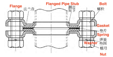
Like other flange connections, stamped flanges use a bolt-based connection system. The assembly includes a flange, a flanged nipple, a gasket, bolts, nuts, and a spring washer (see Figure 2). Unlike traditional flanges, stamped flanges feature a structure with depressions, protrusions, and peripheral flanges, making them distinct from flat designs. The unique design of the flange and flanged nipple—especially the flange itself—sets stamped flanges apart from conventional loose flanges, offering several advantages. These flanges are a non-standard type that, compared to traditional options, provide a simpler structure, more efficient manufacturing processes, and significant reductions in raw material usage and overall costs. Widespread adoption of stamped flanges could result in substantial economic benefits.

Figure 2 Stamped flange assembly
Building on the previous analysis, the Waters method divides the flange into three components: the cylinder, the cone neck, and the flange ring. These are modeled using three different approaches: the cylindrical shell, the linear variable thickness cylindrical shell, and the annular plate. However, the unique structure of the stamped slip-on flange is incompatible with the Waters calculation model. Specifically, the flange’s non-flat design prevents the use of the plate theory method, which is integral to the Waters approach. Therefore, applying the Waters method—designed for non-standard flange verification—to the theoretical calculation of stamped flanges is not feasible.
The unique structure of the stamped flange makes the traditional Waters method unsuitable for theoretical calculations. The author proposes three alternative approaches for calculating stamped flanges and compares their effectiveness:
- Method (a): Calculation using moment theory based on elastic mechanics.
- Method (b): Modeling the stamped flange as a cantilever beam along its circumference, based on the Bach method.
- Method (c): Treating the non-flat flange in the stamped flange assembly as a flat plate of specific thickness, applying moment theory, and verifying using the traditional flat non-standard flange design (referred to as the equivalent calculation method).
Method (a) is theoretically feasible but overly complex, making it impractical for real-world applications. While Method (b) simplifies the calculation, it shares the limitations of the Bach method, such as only accounting for radial bending stress and neglecting circumferential stress, leading to underestimated results. Adding a safety factor could mitigate this, but it would require extensive experimental and simulation analysis, resulting in significant additional effort. Method (c) introduces a novel approach for calculating stamped flanges. Although it may yield different maximum stress positions and values before and after equivalence, it represents a promising direction for the theoretical analysis of non-flat flanges, provided it is validated through finite element analysis and experimental testing.
Related News
- Structural Design and Strength Analysis of a Deepwater Riser Suspension Flange
- Analysis of Heat Dissipation Losses in High-Temperature Flanges and Pipelines Used in Oil Refineries
- Failure and Crack Analysis of an EO/EG Unit Tower Inlet Flange
- Pipe Flange Bolt Tightening in LNG Projects: Key Considerations
- Ultrasonic Testing of High-Neck Flange Welds
- Underwater Flange Connection Methods for Submarine Pipelines
- Key Technologies for Pressure Vessel Testing and Flange Connection Design
- Installation of Main Bolts for Lap Joint Flange in High-Temperature Gas-Cooled Reactors
- Structural Design and Finite Element Analysis of Anchor Flanges
- Key Welding Technology for High-Neck Flange and Steel Pipe Joints
