The Analysis of Causes of Corrosion of SS 304L Flanges
A printing and dyeing equipment factory added water for the pressure test to the pipeline connected to stainless steel 304L raised face flanges. The pressure test water was not emptied in time in the pipeline. After about 15 days, it was found that the flange's sealing surface was corroded. The flanges are sealed with PTFE soft gaskets, and the pipes connected to the flanges are made of stainless steel 316L.
1. Morphology and distribution characteristics of corrosion of flanges
1.1 Macroscopic appearance
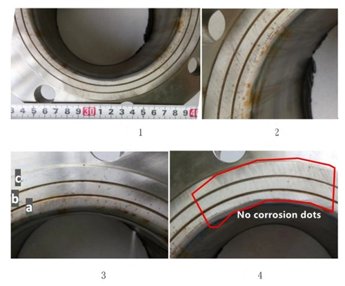
The rust on the flange sealing surface is distributed in dots, and there are strips of rust on the pipe wall at the connection with the flange, and the rust extends along the pipe wall in the direction of the pipe length. The end of the rust on the pipe wall starts from the rust on the flange sealing surface, and the pipe wall is smooth without any rust (Figure 1 and Figure 2). The rust on the pipe wall is caused by the attachment of the corrosion products on the flange sealing surface on the pipe wall. The pipes connected to the flanges are made of stainless steel 316L. The two water lines on the flange sealing surface divide the sealing surface into three ring surfaces a, b and c from the inside to the outside (Figure 3). The inner ring surface (Figure 3a) has denser ring corrosion points and relatively few corrosion dos outwards (Figures 3b and c). About one-sixth of the entire sealing ring face showed no corrosion spots (Figure 4).
1.2 Observation of morphology of corrosion dots
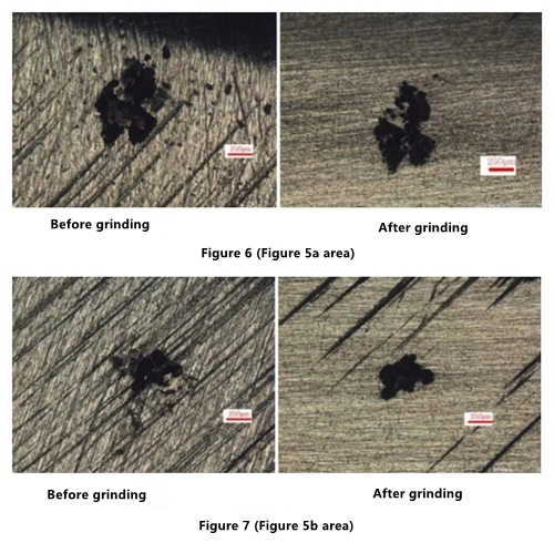
The corrosion dots on the sealing surface before and after grinding with 800# sandpaper is observed by the magnification of 50 along the sealing surface.
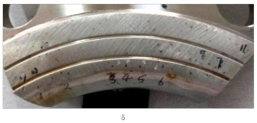
Compared with the larger surface area of the corrosion dot of the inner ring (the a area in Figure 5), the corrosion point area from the inner ring to the outer ring has a small trend of decreasing gradually (Figure 6, Figure 7, and Figure 8). There are scattered smaller corrosion dots around some corrosion points (Figure 6), and some corrosion points have fine filiform corrosion around them (Figures 7 and 8). The morphology of corrosion points is irregular. The appearance of the corrosion point before and after grinding changes little, and the small corrosion point and corrosion wire pattern around the corrosion point can be easily removed by grinding with 800# sandpaper.
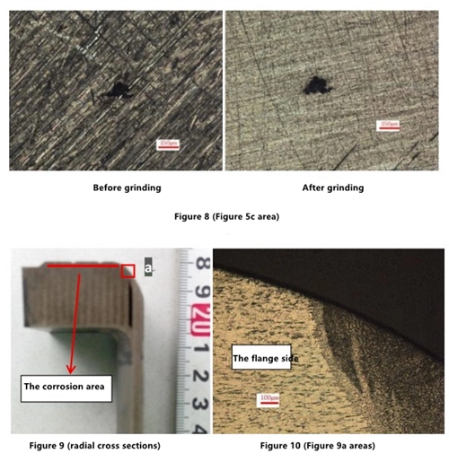
Cut along the radial direction of the flange sealing surface by wire cutting, and observe positions of welding seams and distribution of corrosion points after grinding, polishing and erosion. Corrosion points all occur on the plane of the flange sealing surface. There is also a small number of corrosion points at the connecting part of the flange sealing plane and the transition arc section of the pipeline (located on the flange), and there is no corrosion on the arc surface on the flange side near the welding seam. No corrosion occurred in the pipeline and welding seam area (Figure 2, Figure 5, Figure 9, and Figure 10).
2. Metallographic analysis
The surface of the corrosion point and the cross-section in the thickness direction were sampled, and then placed under a metallographic microscope after inlaying, grinding, polishing, and erosion. No obvious inclusions were found, and the metallographic structure was normal.
2.1 Surface observation of corrosion points
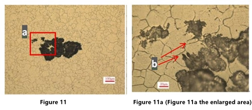
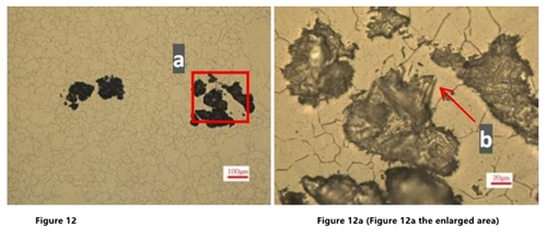
In Figures 11a and 12a, there is a similar antennae like corrosion extending to the periphery at the b part.
2.2 Observation of cross-section of corrosion points
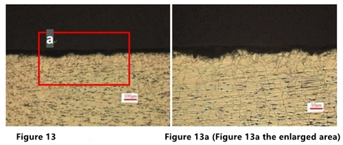
Cut along the thickness direction of the flange, and observe the cross section of the corrosion point. The opening area of the corrosion point is larger than the inside of the corrosion point. The corrosion depth is shallow, with a depth of about 1 to 2 grain sizes (Figure 13 and Figure 13a); there is no abnormality in the metallographic structure, and the grain size is 6.5, which is austenite and a small amount of point-like ferrite structure.
3. The analysis of the composition of flanges and pipes
Samples were taken from the position of the flange sample with corrosion points for chemical composition analysis. The results are shown in Table 1. The detected element content meets the technical requirements of 304L stainless steel. Table 2 shows the chemical composition of the SS 316L pipeline, which meets the standard requirements.
Table 1 Analysis results of the chemical composition of flanges (wt%)
1. Morphology and distribution characteristics of corrosion of flanges
1.1 Macroscopic appearance
The rust on the flange sealing surface is distributed in dots, and there are strips of rust on the pipe wall at the connection with the flange, and the rust extends along the pipe wall in the direction of the pipe length. The end of the rust on the pipe wall starts from the rust on the flange sealing surface, and the pipe wall is smooth without any rust (Figure 1 and Figure 2). The rust on the pipe wall is caused by the attachment of the corrosion products on the flange sealing surface on the pipe wall. The pipes connected to the flanges are made of stainless steel 316L. The two water lines on the flange sealing surface divide the sealing surface into three ring surfaces a, b and c from the inside to the outside (Figure 3). The inner ring surface (Figure 3a) has denser ring corrosion points and relatively few corrosion dos outwards (Figures 3b and c). About one-sixth of the entire sealing ring face showed no corrosion spots (Figure 4).

1.2 Observation of morphology of corrosion dots
The corrosion dots on the sealing surface before and after grinding with 800# sandpaper is observed by the magnification of 50 along the sealing surface.
Compared with the larger surface area of the corrosion dot of the inner ring (the a area in Figure 5), the corrosion point area from the inner ring to the outer ring has a small trend of decreasing gradually (Figure 6, Figure 7, and Figure 8). There are scattered smaller corrosion dots around some corrosion points (Figure 6), and some corrosion points have fine filiform corrosion around them (Figures 7 and 8). The morphology of corrosion points is irregular. The appearance of the corrosion point before and after grinding changes little, and the small corrosion point and corrosion wire pattern around the corrosion point can be easily removed by grinding with 800# sandpaper.
Cut along the radial direction of the flange sealing surface by wire cutting, and observe positions of welding seams and distribution of corrosion points after grinding, polishing and erosion. Corrosion points all occur on the plane of the flange sealing surface. There is also a small number of corrosion points at the connecting part of the flange sealing plane and the transition arc section of the pipeline (located on the flange), and there is no corrosion on the arc surface on the flange side near the welding seam. No corrosion occurred in the pipeline and welding seam area (Figure 2, Figure 5, Figure 9, and Figure 10).


2. Metallographic analysis
The surface of the corrosion point and the cross-section in the thickness direction were sampled, and then placed under a metallographic microscope after inlaying, grinding, polishing, and erosion. No obvious inclusions were found, and the metallographic structure was normal.
2.1 Surface observation of corrosion points
In Figures 11a and 12a, there is a similar antennae like corrosion extending to the periphery at the b part.


2.2 Observation of cross-section of corrosion points
Cut along the thickness direction of the flange, and observe the cross section of the corrosion point. The opening area of the corrosion point is larger than the inside of the corrosion point. The corrosion depth is shallow, with a depth of about 1 to 2 grain sizes (Figure 13 and Figure 13a); there is no abnormality in the metallographic structure, and the grain size is 6.5, which is austenite and a small amount of point-like ferrite structure.

3. The analysis of the composition of flanges and pipes
Samples were taken from the position of the flange sample with corrosion points for chemical composition analysis. The results are shown in Table 1. The detected element content meets the technical requirements of 304L stainless steel. Table 2 shows the chemical composition of the SS 316L pipeline, which meets the standard requirements.
Table 1 Analysis results of the chemical composition of flanges (wt%)
| Element | C | Si | Mn | P | S | Cr | Ni | N |
| Actual values | 0.019 | 0.37 |
1.16 | 0.021 | 0.002 | 18.26 | 8.05 | 0.04 |
| ASTM A240 304L | Less than and equal to 0.03 | Less than and equal to 0.75 | Less than and equal to 2.00 | Less than and equal to 0.045 | Less than and equal to 0.030 | 17.5 to 19.5 | 8.0 to 12.0 | Less than and equal to 0.10 |
Table 2 Analysis results of chemical composition of pipelines (wt%)
| Element | C | Si | Mn | P | S | Cr | Ni | Mo | N |
| Actual values | 0.023 | 0.60 |
1.37 | 0.029 | 0.002 | 16.64 | 10.04 | 2.03 | 0.02 |
| ASTM A240 316L | Less than and equal to 0.03 | Less than and equal to 0.75 | Less than and equal to 2.00 | Less than and equal to 0.045 | Less than and equal to 0.030 | 16.0 to 18.0 | 10.0 to 14.0 | 2.0 to 3.0 | Less than and equal to 0.10 |
4. The analysis of water quality and qualitative analysis of the composition of corrosion products
4.1 The analysis of water quality
The pipeline pressure test water of the plant is the circulating water in the plant. Sampling and testing of water for pipeline pressure test show that the concentration of Cl- in the water is 412mg/L, which is significantly higher than the requirement for chlorine content in the sanitary standards for drinking water (Less than and equal to 250mg/L). There is a certain amount of enrichment of chloride ions in water used for pipeline pressure tests.
4.2 Spectrum (EPMA) analysis of corrosion products
The micro-area composition analysis of the corrosion products at the corrosion point shows that the mass fraction of chlorine content is about 0.32%.
5. Analyses and discussion
5.1 Causes of corrosion
The above observation and analysis of the distribution, morphology and corrosion products of the stainless steel flange corrosion point show that corrosion of the flange has the following characteristics:
(1) About one-sixth of the flange sealing surface has no corrosion point. It is speculated that in the flange tightening process, the bolts in different directions are subjected to uneven force, and the medium in the area with better sealing performance fails to infiltrate and does not cause corrosion.
(2) The distribution of corrosion points on the sealing surface is denser in the inner ring and gradually decreases outward; the apparent area of the corrosion points on the inner ring of the sealing surface is bigger than that of the outer ring. It is speculated that it takes a certain time for the medium to penetrate from the inner ring to the outside, and the crevice where the medium penetrates first begins to corrode; the size of the gap between the inner ring of the flange and the pipe joint is more suitable for crevice corrosion.
(3) Most of the corrosion points are distributed on the flange sealing surface, and there are also a small number of corrosion points at the junction of the sealing surface and the arc section connected to the pipeline, but there is no corrosion point in the transition arc area connected to the pipeline. The reason is that the size of the crevice opening in the arc area at the seal is larger, which is not suitable for crevice corrosion.
(4) The corrosion point is shallow, and the lateral extension is greater than that in the depth direction, which is in line with the characteristics of crevice corrosion.
(5) There is a high concentration of Cl- in the medium, and Cl has the effect of accelerating crevice corrosion. If water storage time for the pressure test is too long, the water in the pipeline does not flow at all, which further aggravates the enrichment of Cl in the crevices and corrosion points. It can be judged that the rust of the flange is caused by the gap in the sealing surface of the flange connection and the crevice corrosion caused by environmental factors based on this. A large amount of Cl- appears in the corrosion products, and the presence of Cl can promote crevice corrosion.
Related News
- Installation of Main Bolts for Lap Joint Flange in High-Temperature Gas-Cooled Reactors
- Structural Design and Finite Element Analysis of Anchor Flanges
- Key Welding Technology for High-Neck Flange and Steel Pipe Joints
- The Design and Calculation of Stamped Lap Joint Flanges
- Development of Manufacturing Large Anchor Flanges
- Hardfacing the Inner Surface of Long-Neck Flanges Using CO₂ Gas-Shielded Welding
- UHV High-Neck Flange Welding
- Application of High-Neck Flange to UHV Steel Pipe Tower
- Analysis of the Cracking Cause of High-Neck Flanges
- Anchor Flanges for the East-West Gas Transmission Project
