Structure and Materials of Anchor Flanges
On this page
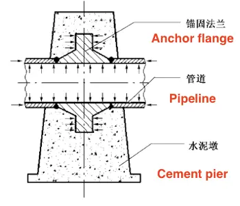
Anchor flanges are key components in long-distance gas (oil) pipeline transmission projects. They are welded onto the main gas (oil) pipelines and secured with cement piers. They are either half-buried or fully buried underground to prevent excessive pipeline displacement caused by combined forces such as self-weight, internal pressure, temperature changes, and changes in pipeline direction and orientation. The underground part of the pipeline is subject to uneven soil and water pressure, while the above-ground part is exposed to natural forces such as wind load, snow load, and earthquakes. Due to the large diameter of the anchor flange (200–1200 mm), high internal pressure (6–12MPa), and wide range of use (spanning more than ten provinces), the reliability demands are extremely high. The flanges also operate under harsh working conditions, including complex geological conditions, varying climates and temperatures, corrosion, vibration, and stringent safety requirements as they pass through densely populated areas like cities, villages, schools, and hospitals. Although several countries are conducting in-depth research on the manufacture and application of anchor flanges, there are few reports available. Since 2002, we have independently conducted research and development on the production technology of large anchor flanges. Through a series of technical breakthroughs, we have achieved new advancements in design calculations, material selection, manufacturing technology, and forming methods for anchor flanges. We have utilized "advanced and applicable" technology to manufacture domestic products, replacing imported ones. These anchor flanges are widely used in key national projects such as the West-East Gas Transmission, Sichuan-East Gas Transmission, Shaanxi-Beijing Line, Huaiwu Line, and West-East Gas Transmission Line 2, meeting urgent national project demands and promoting scientific progress in long-distance gas (oil) pipeline transmission.

Figure 1 Anchor flange working conditions

Figure 1 Anchor flange working conditions
1. Structural Design of Anchor Flanges
Due to the complex stresses on anchor flanges and pipelines, verification of strength, stiffness, fatigue resistance, brittle fracture resistance, and earthquake resistance must be conducted. However, some stresses are currently difficult to calculate accurately, and there is still no unified production standard for anchor flanges. In project design, most follow pressure vessel specifications, refer to relevant standards and practical data to increase the safety margin, and determine the project size through finite element analysis and structural design. First, oil and gas-related industries determine the design coefficient, climate conditions, maximum axial thrust, anchoring form, and other technical parameters based on the medium pressure, usage area, environmental conditions, and other factors related to the anchor flange, and propose technical specification data. On this basis, following the national standards "Gas Pipeline Engineering Design Code" (GB 50251-2003) and "Steel Pressure Vessel" (GB 150-1998), and referring to the American national standards "Pipe Flanges and Flange Fittings" (ASME B16.5-1996, including A1998) and "Gas Transmission and Distribution Pipeline Systems" (ASME B31.8-1999), after detailed theoretical calculations and with relevant production experience, the structural form and key dimensions of the anchor flange are preliminarily designed. The port structural dimensions are then determined by the welding specifications.
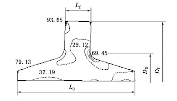
Based on theoretical calculations, the general finite element analysis software MSC.MARC is used to calculate equivalent axial thrust, limit temperature changes, and other data according to the specification task book to understand the working state of the anchor flange. The stress distribution cloud diagram, along with the size and location of concentrated stress, is then obtained, as shown in Figure 2. The stress is linearized, and the stress components are classified and checked, ensuring that strength requirements are met through strength verification. Through stiffness analysis, the allowable displacement is determined to ensure that the flexibility requirements of the cement pier and pipeline are satisfied. To simplify production, in practice, anchor flanges with different working conditions are classified and merged into several major categories. They are then calculated and checked based on the most severe stress conditions, and the structural dimensions are determined accordingly.

Figure 2 Finite element stress analysis (equivalent stress field) and structural design (main dimensions) of anchor flanges
Based on theoretical calculations, the general finite element analysis software MSC.MARC is used to calculate equivalent axial thrust, limit temperature changes, and other data according to the specification task book to understand the working state of the anchor flange. The stress distribution cloud diagram, along with the size and location of concentrated stress, is then obtained, as shown in Figure 2. The stress is linearized, and the stress components are classified and checked, ensuring that strength requirements are met through strength verification. Through stiffness analysis, the allowable displacement is determined to ensure that the flexibility requirements of the cement pier and pipeline are satisfied. To simplify production, in practice, anchor flanges with different working conditions are classified and merged into several major categories. They are then calculated and checked based on the most severe stress conditions, and the structural dimensions are determined accordingly.

Figure 2 Finite element stress analysis (equivalent stress field) and structural design (main dimensions) of anchor flanges
2. Selection of Raw Materials
The "Design Code for Gas Pipeline Engineering" specifies that when pipeline accessories and pipelines are connected by welding, the materials should be the same or similar. Pipeline steel is typically produced through controlled rolling and controlled cooling of API 5L X70 steel, developed by the American Petroleum Institute. It has excellent resistance to dynamic and static loads, can withstand oil and gas erosion and corrosion, and offers strong resistance to hydrogen-induced cracking and sulfide stress corrosion at low temperatures. The raw materials for anchor flanges were initially planned to be the same as pipeline steel, but in practice, producing this type of steel through controlled rolling and controlled cooling proved difficult. Based on the advice of industry experts, the material selection criteria were set to meet performance requirements, ensure compatibility for welding with pipelines, and facilitate smelting and manufacturing. The material is not only advanced and reliable but also suitable for local conditions and easy to produce. Considering various technical factors, the same material as the pipeline was not chosen; instead, the improved CF (crack-free) 62 steel was selected. This steel is a high-strength material with a low-carbon microalloy composition and low sensitivity to welding cracks. Its advantages include not requiring preheating before welding or only needing preheating at 50°C without cracking. It has excellent welding performance and low-temperature toughness, making it suitable for field operations on large components. The improved CF62 has been evaluated for welding quality with X70 pipes, showing no defects in the cross section, and the performance of the welded joints meets the acceptance specifications.
Related News
- Low-Temperature Flange Sealing Solutions for Cryogenic Chemical Pipelines
- Innovative Technology for Automatic Alignment in Underwater Flange Assembly
- Stamped Steel Slip-On Flanges
- Design and Finite Element Analysis of Anchor Flanges for Oil & Gas Pipelines
- Forming and Manufacturing Technology of Anchor Flanges
- Structure and Materials of Anchor Flanges
- Flanges for Pressure Vessels
- An Introduction to Socket Welded Neck Flanges
- Heat Treatment & Mechanical Properties of ASTM A350 LF3 Flanges (Part Two)
- Heat Treatment & Mechanical Properties of ASTM A350 LF3 Flanges (Part One)
