Structural Design and Finite Element Analysis of Anchor Flanges
Anchor flanges are essential components in large-diameter, high-pressure, long-distance gas and oil pipeline systems, operating under complex conditions. This study employs the finite element method for the structural design and analysis of a specific anchor flange, integrating production practices to address design challenges and meet engineering requirements.
The anchor flange has an axisymmetric ring with a central flange, featuring symmetrical flange necks on both sides. During installation, the flange neck ends are welded to the pipeline ends, anchored with cement piers, and subsequently partially or fully buried underground, as depicted in Figure 1. Please note that the arrow direction is for reference only and does not denote a specific orientation. The anchor flange’s primary functions include connecting pipelines, supporting suspended gas pipelines, restricting excessive axial displacement, mitigating load variations caused by internal pressure, temperature fluctuations, or changes in pipeline direction, and ensuring the safety of pipelines and booster pump stations. Anchor flanges are extensively utilized in China's West-East Gas Transmission projects, such as the Sichuan-East Gas Transmission and West-East Gas Transmission Pipeline 2.
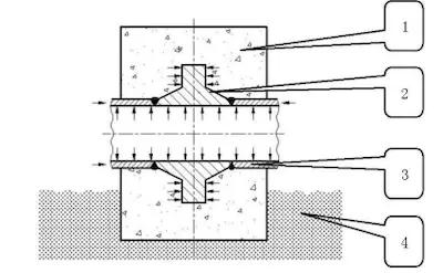
1. Cement pier 2. Anchor flange 3. Gas and oil pipeline 4. Foundation
Figure 1: Schematic diagram of operating conditions of anchor flanges
Considering the complex stresses acting on anchor flanges and pipelines, it is crucial to validate their strength and stiffness, and evaluate their fatigue resistance, brittle fracture toughness, and seismic resilience. Nevertheless, accurately calculating certain stress components remains challenging, leading to ongoing global research efforts. At present, a standardized approach for the structural design of anchor flanges is lacking; consequently, designs are developed based on specific engineering requirements and by referencing analogous product standards. Typically, engineering designs adhere to pressure vessel specifications, consult pertinent standards and empirical data, and utilize finite element analysis to optimize structural designs, improve safety margins, and define engineering parameters. The subsequent example demonstrates the methodology employed in structural design calculations.
According to the technical specifications of the West-East Gas Pipeline Project, the operating conditions for a DN200 anchor flange with a pressure rating of PN6.3 are as follows:
- Design pressure: 6.3 MPa
- Design temperature: -19.01°C
- Maximum design temperature: 42.5°C
- Minimum design temperature: -19.01°C
- Average temperature of the coldest month: 1.7°C
- Total axial thrust: 491 kN
- Wall thickness: 7.5 mm
- Inner diameter: 204 mm
- Outer diameter: 219 mm
- Material Properties:
- Elastic modulus (E): 200,000 MPa
- Poisson's ratio (ν): 0.3
- Compressive strength of cement: 10.34 MPa
- Material: 16Mn steel
- Yield strength (σs): 275 MPa
- Tensile strength (σb): 450 MPa
- Allowable stress: 150 MPa for temperatures ranging from -20°C to 100°C
In accordance with user requirements, the design and analysis of the anchor flange focus on internal pressure and total axial thrust, which include axial stresses induced by temperature variations, internal pressure, and other loading conditions. The stress distribution is shown in Figure 2; only half of the flange is depicted due to its axial symmetry.
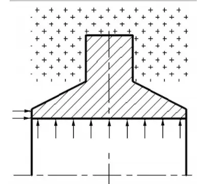
Figure 2: Stress distribution diagram of the anchor flange
In accordance with the technical specifications of the West-East Gas Pipeline Project and pertinent standards—including the "Gas Pipeline Engineering Design Code" (GB50251-2003), "Steel Pressure Vessels" (GB150-1998), "Pipe Flanges and Fittings" (ASME B16.5-1996, with Addenda A1998), and "Gas Transmission and Distribution Pipeline Systems" (ASME B31.8-1999)—we performed comprehensive theoretical analyses and reviewed applicable production data to develop the anchor flange design presented in Figure 3.
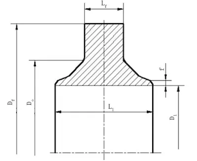
Figure 3: Structural design sketch of anchor flanges
To ensure the safety and reliability of the anchor flange design, we utilized MSC.MARC 2005 to conduct a stress analysis under the specified conditions. Assuming the anchor flange is subjected to axisymmetric stress, the results are presented in Figure 4.
(1) Figure 4 indicates that points A, B, C, and D are critical stress points. The equivalent stress and individual stress component values for each point are detailed in Table 1.

(a) Equivalent stress (b) Axial stress (c) Radial stress (d) Hoop stress
Figure 4: Finite element stress analysis results
Table 1 Stress values on each dangerous point
|
Point |
Equivalent Stress (MPa) |
Axial Stress (MPa) |
Radial Stress (MPa) |
Hoop Stress (MPa) |
Shear Stress (MPa) |
|
A |
85.8 |
-109.4 |
6.0 |
-46.8 |
-0.3 |
|
B |
50.6 |
35.7 |
-17.0 |
10.5 |
-15.5 |
|
C |
105.3 |
-19.9 |
-106.9 |
-20.9 |
-45.5 |
|
D |
48.6 |
-0.2 |
-6.1 |
45.1 |
0.2 |
Note: Negative values indicate compressive stresses or the direction of shear stresses.
(2) The BC segment of the critical path was analyzed, and the equivalent stress and its components along this path are presented in Figure 5. Figure 5 illustrates that the equivalent stress and its components along the BC path are lower than those at points B and C.
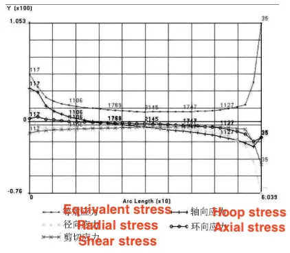
Figure 5: Equivalent stress and stress components along the BC path
(3) Figure 6 depicts the flange deformation under the specified conditions, with a maximum deformation of 0.02628 mm occurring at the flange neck.
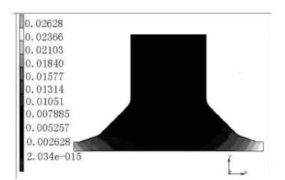
Figure 6: Deformation magnitude
The finite element analysis reveals that, except for elevated stress values at critical points A, B, C, and D (stress concentration zones), stress components at other locations remain relatively low, with absolute values not exceeding 110 MPa. These findings align with the requirements of GB150-1998, which stipulate that stresses in each category of the integral flange should be below their respective allowable limits, and that shear stress should not exceed 80% of the allowable stress. Additionally, the flange provides significant axial restraint to the welded pipe, resulting in a maximum deformation of 0.026 mm. The dimensions of the designed anchor flange are optimized to meet project requirements effectively. Currently, the flange operates reliably within the West-East Gas Pipeline System.
Related News
- Installation of Main Bolts for Lap Joint Flange in High-Temperature Gas-Cooled Reactors
- Structural Design and Finite Element Analysis of Anchor Flanges
- Key Welding Technology for High-Neck Flange and Steel Pipe Joints
- The Design and Calculation of Stamped Lap Joint Flanges
- Development of Manufacturing Large Anchor Flanges
- Hardfacing the Inner Surface of Long-Neck Flanges Using CO₂ Gas-Shielded Welding
- UHV High-Neck Flange Welding
- Application of High-Neck Flange to UHV Steel Pipe Tower
- Analysis of the Cracking Cause of High-Neck Flanges
- Anchor Flanges for the East-West Gas Transmission Project
