Stamped Steel Slip-On Flanges
Abstract
The steel stamped slip-on flange is a new, non-standard pipe flange. This paper introduces the slip-on flange and details its structure and characteristics. A model is created using SolidWorks 3D modeling software and imported into ANSYS Workbench for finite element analysis. The slip-on flange is then evaluated based on the stress strength criteria outlined in JB 4732. The results provide insights that can guide the further promotion and optimization of stamped slip-on flanges.
Bolted flanges are the most commonly used type in petrochemical equipment, containers, and pipelines. The pipe flange is essential for connecting pipelines to fluid equipment, including valves, and serves as a sealing element that withstands pressure. The steel stamped slip-on flange, with its unique, specially shaped structure, offers significant advantages, including simplified processing and reduced raw material consumption, making it highly valuable for widespread adoption. However, due to the absence of relevant national standards, stamped slip-on flanges have not been widely integrated into engineering applications. This paper addresses the challenge of meeting the growing demand for stamped slip-on flanges, which is hindered by the lack of reliability verification, national standards, and detailed analysis. The paper first introduces the stamped slip-on flange, followed by finite element analysis and stress classification using 3D modeling and finite element software. The flange is then evaluated according to the stress strength criteria in JB 4732, confirming its strength reliability and supporting its promotion and use while providing guidance for its optimized design.
1. Stamped Slip-On Flanges and Their Structure and Characteristics
1.1 Origin of Stamped Slip-On Flanges
Stamped flanges have been used since the late 1970s, primarily in pressure vessels designed for pressures below 1.0 MPa and temperatures under 200°C. These flanges are now commonly used in dyeing machines. For example, dyeing machines from the German company TC were among the first pressure vessels to incorporate stamped flanges. This design was later widely adopted by the dyeing machine industry. Dyeing machines manufactured by Lixin Dyeing and Finishing Machinery Co., Ltd., a subsidiary of Lixin Industrial Co., Ltd., use stamped slip-on concave pipe flanges.
1.2 Structure and Characteristics of Stamped Slip-On Flanges
As shown in Figures 1 and 2, the stamped slip-on flange assembly typically consists of a flange, flanged nipple, gasket, bolt, nut, and spring washer. The key difference between stamped slip-on flanges and other types is the flange's non-planar, specially shaped structure, specially shaped structure, which includes concave, convex, and flanged elements, providing distinct advantages such as reduced material consumption and simplified manufacturing.
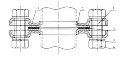
- Flange
- Stub End
- Bolt
- Gasket
- Spring Washer
- Nut
Figure 1: Stamped slip-on flange assembly
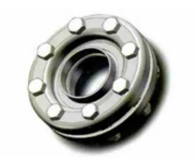
Figure 2: Stamped slip-on flange structure
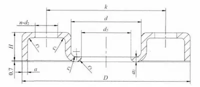
Figure 3: Dimension of stamped slip-on flange
1.2.2 Characteristics of Stamped Flange
The unique structure of the stamped flange results in the following key characteristics:
- The specially shaped structure of the flange enables a significant reduction in thickness while maintaining rigidity, thereby considerably reducing raw material consumption. For example, a DN50 and PN1.0 MPa flange typically has a thickness of 20 mm in the case of a standard flat-welded loose-fitting steel pipe flange. In contrast, the stampled loose-fitting flange has a thickness of only 4 mm, with a flange wall thickness of 3.5 mm for the short section and a weld end wall thickness of 2.6 mm.
- Both the flange and the flanged nipple are directly stamped from plate material. Except for the waterline on the sealing surface of the flanged nipple, no additional machining is required for the stamped slip-on flange, resulting in reduced processing and manufacturing costs.
- Due to the non-flat structure of the stamped slip-on flange, the non-standard flange calculation method outlined in GB 150-1998 'Steel Pressure Vessels' cannot be fully applied for design and analysis, limiting its adoption in China.
2. Finite Element Analysis of Stamped Slip-On Flange
2.1 Model Size and Material Properties
2.1.1 Model Size
For the finite element analysis, the dimensions of the DN80 stamped slip-on flange are shown in Figure 3 and Table 1. The dimensions of the flanged nipple are shown in Figure 4 and Table 2.
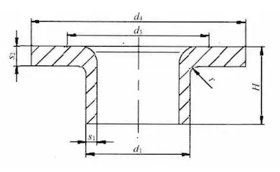
Figure 4 The dimensions of flange joint
Table 1 Flange dimensions
|
Parameter |
Value |
Unit |
Description |
|
Nominal Diameter (DN) |
80 |
mm |
It corresponds to the standard pipe size, which defines the flange dimensions. |
|
Flange Outer Diameter (D) |
200 |
mm |
The total outer diameter of the flange ensures compatibility with pipe connections. |
|
Bolt Hole Center Circle Diameter (K) |
160 |
mm |
The diameter of the circle that passes through the center of each bolt hole determines the bolt hole arrangement. |
|
Bolt Hole Diameter (d₃) |
17.5 |
mm |
The diameter of each bolt hole usually matches the size of the selected bolts. |
|
Number of Bolt Holes (n) |
8 |
- |
The flange typically has 4, 6, or 8 bolt holes, depending on the design standards. |
|
Thread (Th) |
M16 |
- |
The thread specification for the bolts |
|
Flange Height (H) |
23.0 |
mm |
The thickness or height of the flange is crucial for its strength and load-bearing capacity. |
|
Flange Inner Diameter (d₅) |
94.0 |
mm |
The inner diameter of the flange usually matches the pipe’s outer diameter to ensure a proper seal. |
|
Flange Thickness (a) |
5.0 |
mm |
The overall thickness of the flange material affects both its strength and sealing ability. |
|
a₂ (Specific Thickness) |
4.3 |
mm |
The thickness in a specific area of the flange may refer to a particular section or support region. |
|
d (Diameter) |
123 |
mm |
The diameter of a specific part of the flange is often related to the sealing or mating surface. |
|
r₁ (Radius) |
4.5 |
mm |
The radius of a rounded feature on the flange, such as the outer edge or internal corner, defines its shape and geometry. |
|
r₃ (Radius) |
5.0 |
mm |
The radius of another rounded feature may be related to the bolt holes or other sections of the flange. |
Table 2 Dimensions of flanged spool
|
Parameter |
Value |
Unit |
|
Nominal Diameter (DN) |
80 |
mm |
|
Flange Joint Height (H) |
23 |
mm |
|
Flange Joint Outer Diameter (d₄) |
138 |
mm |
|
Flange Joint Neck Outer Diameter (d₁) |
88.9 |
mm |
|
Rounded Corner (r) |
5.0 |
mm |
|
Diameter of Center Circle of Dense Groove Waterline (d₃) |
100 |
mm |
|
Flange Joint Weld End Wall Thickness (s₁) |
3.2 |
mm |
|
Flange Joint Flange Wall Thickness (s₂) |
4.0 |
mm |
2.1.2 Material Properties
The flange is made from 1Cr18Ni9Ti, while the bolt and nut are made from 40MnB. The material properties are provided in Table 3.
Table 3 Material properties
|
Components |
Materials |
Young's Modulus (E) |
Poisson's Ratio (μ) |
Allowable Stress Intensity (σᵦ (150))
|
Allowable Stress Strength (Sₘ) |
|
Flange |
1Cr18Ni9Ti |
1.93 × 10⁵ MPa |
0.3 |
103 MPa |
34.3 MPa |
|
Butt Welding Ring |
Not provided |
Not provided |
Not provided |
Not provided |
Not provided |
|
Bolt |
40MnB |
2.11 × 10⁵ MPa |
0.3 |
171 MPa |
57 MPa |
|
Nut |
2.2 Finite Element Model and Mesh Division
2.2.1 Finite Element Model
For the DN80 model, the design pressure is 1.0 MPa, and the design temperature is 150°C. To simplify the calculation and improve efficiency, a 1/8 sector of the joint is used as the finite element model, based on the symmetry of the flange joint system, as shown in Figure 5. The model consists of four components: the flange, flanged short section, bolt, and nut, with a contact pair representing the gasket. Non-separation contact is applied between the bolt and nut to prevent relative sliding. Frictionless contact is applied between the bolt and flange, and between the flange and flanged short section.
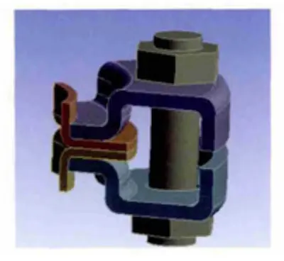
Figure 5 Finite element model of pressed slip-on flange
2.2.2 Mesh Division
Since the flanged short section and nut in the flange joint are sweepable bodies, the sweeping method is used for mesh generation, primarily producing hexahedral meshes (with 8-point hexahedral elements for higher accuracy) or prismatic meshes. The flange is meshed using a hexahedral-dominant approach, with hexahedral meshes generated externally and tetrahedral meshes generated internally as needed. Due to the unsuitability of this method for meshing slender geometric bodies, the bolts are meshed using an automatic meshing method, which switches between tetrahedral and sweeping methods as required. Once the meshing method is determined, the mesh size is refined to achieve optimal results, which are achieved when the mesh size is set to 0.0025 mm. The meshing results are shown in Figure 6.

Figure 6 The display of mesh
2.3 Load and Boundary Condition Settings
Internal pressure and preload are applied to the flange based on actual operating conditions. The following boundary conditions are specified:
- Internal Pressure: A uniform internal pressure of 1.0 MPa is applied to simulate the stress distribution in the flange under operational conditions.
- Preload: The bolt preload is calculated according to standard flange bolt connection requirements and applied to ensure the integrity of the flange seal.
- Constraints: Fixed boundary conditions are applied to the bolt holes in the flange to simulate the stress state after the bolts are tightened. Additionally, displacement constraints are applied to the welded end of the flanged short section to prevent any rigid body movement from affecting the calculation results.
2.4 Stress Analysis and Classification
Stress analysis and classification are conducted according to JB 4732-1995, 'Steel Pressure Vessels – Analysis and Design Standards.' Finite element analysis is used to determine the equivalent stress distribution of the stamped slip-on flange under operating conditions, followed by stress classification as per JB 4732:
- Primary Membrane Stress (Pm): This stress arises from internal pressure and is related to the overall structure of the flange. It must meet the stress strength verification standard.
- Primary Bending Stress (Pb): Due to the non-flat structure of the flange, partial bending stress is more significant, especially in the transition zone between the flange and the flanged short section.
- Secondary Stress (Q): This stress results from bolt preload and partial structural deformation. It should be kept within the allowable range to prevent fatigue failure.
The analysis shows that the maximum equivalent stress of the stamped slip-on flange occurs in the raised area of the flange and the transition zone of the flanged short section. However, all stress values are below the allowable material stress specified in JB 4732, confirming that the flange satisfies the strength requirements under the design conditions.
2.5 Calculation Results and Optimization Suggestions
The results of the finite element analysis indicate that the stamped slip-on flange can withstand both internal pressure and bolt preload under the design conditions, with stress levels within the allowable limits specified by the standards. To optimize the design further, the following recommendations are provided:
- Refine the flange thickness: Reduce the partial thickness while maintaining stiffness to lower material costs.
- Enhance the flanged short section: Improve fatigue resistance in the stress concentration areas through partial strengthening.
- Experimental validation: Use methods such as hydraulic testing or bolt connection performance tests to validate the reliability of the results.
Related News
- Low-Temperature Flange Sealing Solutions for Cryogenic Chemical Pipelines
- Innovative Technology for Automatic Alignment in Underwater Flange Assembly
- Stamped Steel Slip-On Flanges
- Design and Finite Element Analysis of Anchor Flanges for Oil & Gas Pipelines
- Forming and Manufacturing Technology of Anchor Flanges
- Structure and Materials of Anchor Flanges
- Flanges for Pressure Vessels
- An Introduction to Socket Welded Neck Flanges
- Heat Treatment & Mechanical Properties of ASTM A350 LF3 Flanges (Part Two)
- Heat Treatment & Mechanical Properties of ASTM A350 LF3 Flanges (Part One)
