Installation of Main Bolts for Lap Joint Flange in High-Temperature Gas-Cooled Reactors
This paper outlines the process for installing and positioning the main bolts on the lap joint flange of the hot gas duct in high-temperature gas-cooled reactors. By utilizing precise installation techniques and specialized positioning tools, we ensure accurate alignment of the main bolts and the bolt tensioning machine. This precision facilitates even distribution of stress across the metal sealing gasket of the hot gas duct, thereby maintaining its sealing integrity.
High-temperature gas-cooled reactors (HTGRs) are internationally recognized for their excellent safety features, high thermal efficiency, deep fuel utilization, and high conversion ratios. In HTGRs, helium acts as the heat transfer medium. High-temperature helium circulates within the primary loop, while the pressure boundary of the secondary loop comprises the reactor pressure vessel, the steam generator pressure vessel, and the hot gas duct shell that connects these vessels. Flange connections are used to prevent radioactive material leakage, ensuring environmental protection.Before applying load to the flange, the bolt preload is set to achieve the required gasket compression, though it may not exactly equal the gasket preload. During operation, factors such as pressure, temperature, external forces, torque, and the medium affect the residual gasket load, final compression, and circumferential compression uniformity, all of which directly impact joint sealing. Experience shows that most bolted flange joint leaks result from insufficient bolt installation loads. Therefore, the sealing effectiveness and safety of flange joints throughout their lifecycle depend heavily on the bolt preload's magnitude, uniformity, and stability. Bolt preload uniformity is influenced by several factors, with flange design, installation processes, and manufacturing precision being the most critical.
This discussion focuses on the installation and positioning methods for the lap joint flange of the HTGR hot gas duct shell. By enhancing the positioning accuracy of the lap joint flange's main bolts, the pre-tightening load of the 42 main bolts is evenly distributed.
The primary circuit's pressure boundary includes the reactor pressure vessel, steam generator pressure vessel, hot gas duct, and its casing. In a 10 MW high-temperature gas-cooled reactor, the primary helium coolant follows this path:
Pressurization: Helium at 250 °C is pressurized by the main circulation fan.
Core Entry: The pressurized helium enters the lower section of the reflector layer adjacent to the core through the outer ring pipe of the hot gas duct.
Ascent and Descent: It moves upward through graphite block perforations to the cavity above the core, then flows downward through the core, absorbing heat.
Heating: Upon heating, the helium's temperature rises to 700 °C.
Steam Generation: The hot helium enters the hot gas header at the reactor's base, mixes thoroughly, and proceeds through the central ring pipe of the hot gas duct to the steam generator. Here, it transfers heat to the secondary-side water, producing steam with specified parameters.
Cooling and Recirculation: The helium cools back to 250 °C and returns to the main circulation fan's inlet, maintaining a closed-loop cycle within the primary circuit.
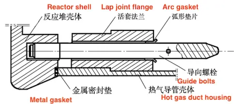
The flange surface of the hot gas duct casing is sealed with a double-pass metal sealing ring, secured by 42 evenly distributed bolts that apply the necessary pre-tightening force. Unlike standard bolted flange joints, the unique design of the high-temperature gas-cooled reactor requires a horizontal arrangement of the hot gas duct. After pre-tightening the main bolts, the assembly of bolts, nuts, and metal sealing rings in the lap joint flange of the hot gas duct housing forms a complex nonlinear system. In this horizontal setup, gravity causes the threaded end's axis to deviate from being perpendicular to the flange surface during the main bolt's horizontal installation. Therefore, auxiliary tooling is necessary to adjust, stretch, and pre-tighten the bolt. Specialized installation and positioning equipment ensures coaxial alignment of bolts and screw holes, facilitating proper installation of circumferentially distributed flange bolts.
Misalignment of the lap joint flange surface during assembly, such as non-concentricity or non-parallelism, can cause uneven sealing surface forces during bolt tightening, leading to mechanical damage and joint leakage. During assembly, first adjust the lap joint flange. Use the main crane to horizontally position the lap joint flange into the hot gas duct shell, ensuring both components are aligned. Align the guide bolt holes and secure the flange with three guide bolts before installing the remaining bolts. Once the lap joint flange is fixed, insert the arc gasket. Use the flange's inner hole to align the bolt hole axis perpendicular to the flange surface. Install bolts in the remaining holes, make final adjustments, and remove the arc gasket.
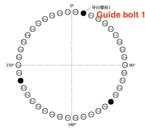
The lap joint flange of the hot gas duct shell consists of 42 main bolts, nuts, and gaskets. The assembly sequence of the bolts is crucial to minimize interference between bolts and ensure even distribution of load. Based on the bolt numbering sequence, the bolts are divided into four groups for installation: Group 1 (20 bolts), Group 2 (13 bolts), Group 3 (6 bolts), and Group 4 (3 bolts).

Figure 1: Schematic Diagram of the lap joint flange tooling installation

Figure 2: Grouping Scheme of Main Bolts
Step 1: Installation of Group 1 (20 bolts)
Begin by installing the 20 M90 main bolts of the lap joint flange in Group 1 (Figure 2). The installation of the bolts, nuts, and gaskets involves the following steps:
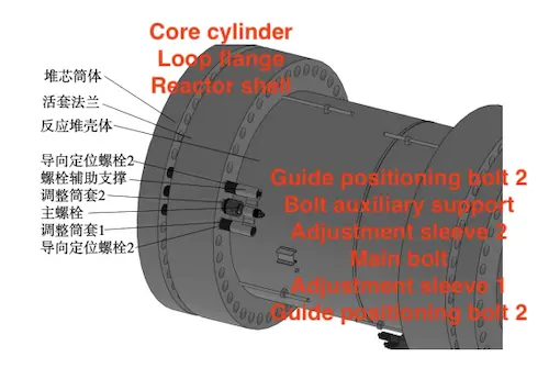
First, use an auxiliary rotation tool to install positioning guide bolts 1 and 2 at the 90° position. Insert adjustment copper sleeve 1 into the lap joint flange through hole to align the guide bolts, ensuring their axes are perpendicular to the flange surface.
Step 2: Main Bolt Installation
- Before installing the main bolt, apply protective tape to the front and back sections of the bottom M90 bolt. Thread the sleeve into the end M68 bolt to the correct position to prevent thread damage during installation.
- Lift the main bolt to the installation position and manually align it. Remove the protective tape from the front and install adjustment copper sleeve 2.
- Install the bolt support fixture, then use the auxiliary rotation device to position the bolt.
- Remove the second section of protective tape, thread the bolt to the bottom, remove the rotating wrench, and withdraw the adjustment copper sleeve.
- Manually install the washer and nut for the main bolt, ensuring alignment with the bolt support. Tighten the main nut and remove the support fixture.
Step 3: Alignment and Verification
- Verify the vertical alignment of the main bolt axis with the lap joint flange surface. Once the first bolt is installed and positioned, remove a guide positioning bolt, fix it in the next screw hole, and repeat the steps to install the remaining 20 bolts.
Group 2 (13 bolts), Group 3 (6 bolts), and Group 4 (3 bolts)
- Repeat the installation steps for Group 2 using the already installed main bolts.
- Remove 3 guide bolts and repeat the process to install the remaining 6 bolts in Group 3 and 3 bolts in Group 4 (Figure 3).
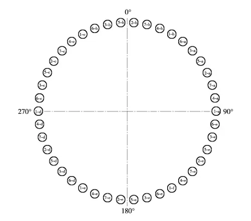
Flange bolt connections requiring high sealing performance necessitate the use of bolt tensioning machines for pre-tightening. During staged pre-tightening of multiple bolts, bolts tightened subsequently can affect the pre-tightening force of those tightened earlier. The proximity of bolts influences this effect; closer bolts experience a greater load-sharing impact, significantly reducing the pre-tightening force in earlier tightened bolts. Based on established practices, the 42 M90 pre-tightening bolts are organized into seven groups, each containing six bolts. Utilizing the installed main bolt positioning stretching machine, six bolts are simultaneously tensioned to ensure precise and uniform bolt stretching (see Figure 4).

Figure 3: Schematic Diagram of Main Bolt Installation

Figure 4: Grouping Scheme of Main Bolt Stretching Machine
The auxiliary installation and positioning equipment for the main bolts of the high-temperature gas-cooled reactor's hot gas duct shell is designed for horizontally arranged flange bolts. It ensures the coaxiality of bolts with screw holes in the horizontal state, simplifying the installation of circumferentially arranged bolts. The safety and reliability of the bolt flange joint seal depend on the flange's sealing design, bolt tensioning method, and installation process. Before tensioning and pre-tightening the main bolts of the reactor's lap joint flange, the installation sequence and auxiliary tooling ensure uniform load distribution after pre-tightening.
Related News
- Installation of Main Bolts for Lap Joint Flange in High-Temperature Gas-Cooled Reactors
- Structural Design and Finite Element Analysis of Anchor Flanges
- Key Welding Technology for High-Neck Flange and Steel Pipe Joints
- The Design and Calculation of Stamped Lap Joint Flanges
- Development of Manufacturing Large Anchor Flanges
- Hardfacing the Inner Surface of Long-Neck Flanges Using CO₂ Gas-Shielded Welding
- UHV High-Neck Flange Welding
- Application of High-Neck Flange to UHV Steel Pipe Tower
- Analysis of the Cracking Cause of High-Neck Flanges
- Anchor Flanges for the East-West Gas Transmission Project
