Innovative Technology for Automatic Alignment in Underwater Flange Assembly
Abstract: With the continued development of oil resources in deepwater areas, submarine pipeline transportation is widely recognized as the fastest, safest, most economical, and most reliable method. As the number of submarine pipelines increases, connecting pipelines on the seabed has become inevitable. However, in deepwater environments, human intervention is not possible for related auxiliary tasks. Therefore, we have designed an underwater bolted flange connection machine capable of connecting pipelines with the assistance of an ROV. When connecting pipelines on the seabed, the first challenge to address is the alignment of the pipelines. This paper primarily analyzes and describes the alignment process of the underwater bolted flange connection machine.
With the advancement of science and technology, the global demand for oil continues to grow across various countries and regions. Meanwhile, as land-based oil resources become increasingly depleted, it is becoming difficult to meet the rising demand. Therefore, tapping into the abundant oil and gas reserves beneath the sea has become an inevitable trend. According to geological predictions, deepwater regions hold more than 70% of the world’s oil and gas resources. It is preliminarily estimated that deepwater areas contain as much as 100 billion barrels of oil, making them a key replacement area for the world’s oil and gas resources. Exploration results show that the South China Sea is rich in oil and gas resources. The most common, safe, economical, and reliable method for transporting oil and gas is through submarine pipelines. As a result, submarine pipelines are essential for the exploitation of oil and gas in deepwater areas.
Whenever a newly developed oil field is completed, it is essential to integrate it into the existing pipeline system to fully utilize the built pipelines and enhance resource efficiency. At the same time, due to the harsh environment of deepwater areas, pipelines are inevitably damaged over time, either due to their extended service life or the impact of accidents. For these reasons, connecting pipelines in deepwater areas becomes unavoidable. However, human intervention is not feasible for related auxiliary work in such environments. Therefore, an underwater bolt flange connection machine has been designed to assist in connecting pipelines with the help of an ROV. The first challenge when connecting pipelines on the seabed is ensuring proper alignment. This article primarily analyzes and describes the process of pipeline alignment using the underwater bolt flange connection machine.
1. Precision Alignment Process
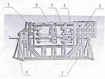
The structure of the bolt flange connection tool is shown in the figure. It mainly consists of a guide tool, bolt storage unit, axial alignment tool, nut storage unit, inner base, clamping claw, tensioner storage unit, and other components.

1. Bolt library 2. Claw 3. Nut library 4. Tensioner library 5. ROV control panel 6. Pipeline 7. Frame
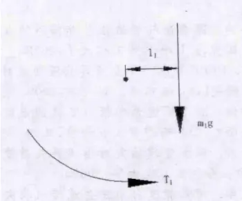
Figure 1: Torque Analysis Diagram of the Nut Library
The nut library serves two main functions: it holds the nuts, and its integrated probe can be inserted into the bolt hole of the lap joint flange to rotate it along with the nut library, enabling precise alignment of the lap joint flange with the bolt holes of the fixed flange.
The working process is as follows:
① The horizontal hydraulic cylinder drives the nut library to move horizontally, causing the probe to gradually approach the lap joint flange.
② The swing hydraulic cylinder rotates the gear shaft, which in turn rotates the nut library around the pipeline axis via the gear ring. At the same time, the ROV monitors the position of the paint strips on the front baffle of the nut library and the lap joint flange. When the paint strips on the nut library align with those on the lap joint flange—indicating that the probe is aligned with the bolt hole of the lap joint flange—the swing hydraulic cylinder stops and maintains its position.
③ The horizontal hydraulic cylinder continues to move the nut library horizontally, allowing the probe to be inserted into the bolt hole of the lap joint flange.
④ The swing hydraulic cylinder continues to operate, driving the nut library to rotate around the pipeline axis. During this process, the lap joint flange rotates along with the probe. Simultaneously, the position of the paint strips on the lap joint flange and the fixed flange is monitored via the ROV. When the paint strips on both flanges are aligned, it indicates that the bolt holes of the fixed flange and the lap joint flange are preliminarily aligned. The swing hydraulic cylinder then stops operating and maintains its current position.
⑤ The horizontal hydraulic cylinder drives the nut library to move horizontally again, allowing the front end of the probe to be inserted into the bolt hole of the fixed flange, thereby completing the alignment process.
In order for the gear shaft to drive the nut library to rotate, the torque (T1) provided by the swing hydraulic cylinder must satisfy:
T₁ = m₁g l₁ (1)
Where:
m₁ — the mass of the nut library.
l₁ — the horizontal distance from the center of mass of the nut library to the axis of the pipeline.

Figure 2: Torque Analysis of the Nut
Similarly, in order for the gear shaft to drive the bolt library to rotate (ensuring that the bolts and nuts remain coaxial at all times), the torque T2 provided by the swing hydraulic cylinder must satisfy:
T2=m2gl2 (2)
Where:
m2 — the mass of the bolt library
l2 — the horizontal distance from the center of mass of the bolt library to the axis of the pipeline
To enable the gear shaft to drive the tensioner magazine to rotate and keep the tensioner and the nut coaxial, the torque Ts provided by the swing hydraulic cylinder must satisfy:
T3=m3gl3 (3)
Where:
m3 — the mass of the tensioner magazine
l3 — the horizontal distance from the center of mass of the tensioner magazine to the pipeline axis
In summary, to enable the nut magazine, bolt magazine, and tensioner magazine to rotate together around the pipeline axis, the total torque T provided by the swing hydraulic cylinder must satisfy:
T=n(T1+T2+T3) (4)
Where:
n — safety factor (considering factors such as friction and dynamic load).
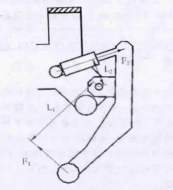
Before the nut magazine can perform precision alignment, it is essential to ensure that the two pipeline sections to be connected are coaxial. Rough alignment alone is insufficient to meet the required accuracy, and further adjustment must be carried out using the claw mechanism. When the claws close, they grip the flange tightly through rollers, ensuring that the flange axes are concentric. This provides the necessary conditions for the subsequent fine alignment operation performed by the nut magazine.
Balance Relationship of the Axial Force of the Jaws
The axial force F1 provided by the jaws must satisfy the torque balance equation:
F1L1=F2L2 (5)
That is:
F1=L2F2L1(6)
Where:
F1 — axial clamping force provided by the jaws
L1 — arm of the axial force
F2 — thrust of the hydraulic cylinder
L2 — distance from the hydraulic cylinder’s point of action to the rotation center

Figure 3 Axial force of the Jaws
2. Rough Alignment Process
To enable the fine alignment of the bolt flange connection machine, rough alignment must first be carried out. The primary purpose of rough alignment is to position the two pipelines to be connected in close proximity, creating favorable conditions for precise alignment. This process is mainly accomplished using the axial alignment tool, the ROV, and the connection device.
The workflow is as follows:
① The mothership places the receiving tool and the axial alignment tool near the two pipelines to be connected, preparing for the next step.
② The ROV is operated to dock with the receiving tool, and then places it onto the pipeline on the fixed flange side.
③ The ROV undocks from the receiving tool, docks with the axial alignment tool, and places it onto Pipe 2 on the lap joint flange side.
④ The ROV undocks from the axial alignment tool, then connects the receiving tool with the axial alignment tool with the help of its manipulator (i.e., inserting the piercing anchor on the axial alignment tool into the corresponding socket on the receiving tool).
⑤ The ROV, carrying the winch, docks with the alignment tool again, and the winch is used to pull the cable, drawing the pipe on the fixed flange side closer to the pipe on the lap joint flange side.
⑥ Once the axial alignment tool is docked with the receiving tool, the rough alignment process is completed.
3. Conclusion
The alignment of bolted flanges is the first and most critical step in achieving a successful flange connection. Accurate alignment of the bolted flange connector is essential to ensure proper assembly. This article outlines the alignment process of the underwater bolted flange connection machine. The machine is capable of completing the alignment independently, without the need for human intervention, and fully meets the technical requirements for bolted flange connections. This lays a solid foundation for the subsequent connection operations.
Related News
- Low-Temperature Flange Sealing Solutions for Cryogenic Chemical Pipelines
- Innovative Technology for Automatic Alignment in Underwater Flange Assembly
- Stamped Steel Slip-On Flanges
- Design and Finite Element Analysis of Anchor Flanges for Oil & Gas Pipelines
- Forming and Manufacturing Technology of Anchor Flanges
- Structure and Materials of Anchor Flanges
- Flanges for Pressure Vessels
- An Introduction to Socket Welded Neck Flanges
- Heat Treatment & Mechanical Properties of ASTM A350 LF3 Flanges (Part Two)
- Heat Treatment & Mechanical Properties of ASTM A350 LF3 Flanges (Part One)
