Design and Finite Element Analysis of Anchor Flanges for Oil & Gas Pipelines
Abstract
Anchor flanges are critical components in oil and gas pipeline engineering, requiring precise design and calculation to account for complex engineering factors. Traditional design methods often rely on conventional calculation approaches, resulting in suboptimal structural dimensions, excessive partial stress, and insufficient optimization. This study examines a high-pressure, large-diameter anchor flange, combining theoretical calculations with finite element analysis to systematically design and optimize its structure. The analysis shows that maximum stress occurs at the flange fillet and neck, with lower stress in other areas. The strength assessment confirms compliance with design standards. The findings demonstrate that optimizing anchor flange design using finite element analysis enhances structural integrity and ensures compliance with technical standards across various engineering applications.
Keywords: anchor flange, finite element analysis, structural design, stress analysis, and design optimization
1. Introduction
In oil and gas pipeline engineering, anchor flanges are essential for preventing axial thrust from damaging valve chambers and other equipment. They are widely used in large-diameter, high-pressure, long-distance pipelines, particularly at pipeline terminals. Their primary functions include fixing the pipeline, limiting axial displacement, and protecting above-ground pipelines and station equipment. Anchor flanges are commonly applied in major Chinese pipeline projects, such as the West-East Gas Transmission Project and its second phase. Despite their crucial role in pipeline design and manufacturing, current anchor flange designs rely on standard flange specifications and conventional dimensional data, lacking in-depth mechanical analysis and optimization. Design calculations tend to be conservative and often lack finite element analysis support, which can result in excessive partial stress in critical areas, particularly the flange fillet and pipe neck, potentially creating safety risks. Therefore, integrating finite element analysis into anchor flange design optimization remains a key challenge in modern engineering practice.
2. Anchor Flange Structural Design
2.1 Structural Form
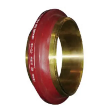
The anchor flange is an axisymmetric ring forging, and its structural design must meet various mechanical performance requirements. It generally consists of a flange body and flange necks, with the flange necks welded to the pipeline and embedded in the anchor pier. Traditionally, anchor flanges are connected using bolts and gaskets. However, to improve connection reliability and streamline installation, modern designs often eliminate bolts and gaskets, using welded connections to form an integral flange. This approach not only strengthens the bond between the flange and the pipeline but also reduces axial thrust, preventing damage to station equipment and ensuring pipeline stability. Figure 1 illustrates the structure of the anchor flange.

Figure 1: Structure of an anchor flange
2.2 Force Analysis
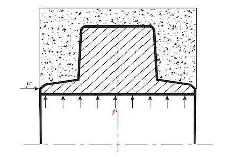
The design of an anchor flange must consider complex loading conditions, including internal pressure and axial thrust due to temperature variations and pipeline pressure (Figure 2). As a critical pipeline component, the anchor flange experiences non-uniform load distribution throughout the flange. Stress concentrations are most pronounced at the flange fillet and pipe neck, requiring careful design attention.

Figure 2: Schematic diagram of anchor flange stress
3. Finite Element Analysis and Design Optimization
3.1 Design Parameters
This study uses a DN1200 PN 12.0 MPa anchor flange as a case study for finite element analysis (Table 1). The design considers load conditions, including internal pressure of 12 MPa and an axial thrust. The analysis results guide further optimization of the flange design.
Table 1: Design Parameters for PN12.0 MPa DN1200 Anchor Flange
| Parameter | Value |
|---|---|
| Flange Type | DN1200 PN 12.0 MPa |
| Case Study | Finite Element Analysis |
| Design Considerations | Load Conditions (Internal Pressure and Axial Thrust) |
| Internal Pressure (MPa) | 12.0 |
| Axial Thrust | To be defined based on analysis |
| Purpose | Flange Design Optimization based on Analysis Results |
3.2 Finite Element Model and Calculation
To accurately simulate the stress conditions of the anchor flange, the SOLID45 element type is used for finite element analysis. Due to the flange’s axisymmetric nature, the model is reduced to a quarter model, with mesh refinement applied to areas of stress concentration, particularly at the flange fillet and pipe neck. This approach ensures accurate stress distribution and helps identify potential structural issues.
3.3 Result Analysis and Optimization
Finite element analysis results indicate that maximum axial stress occurs at the flange neck, while maximum combined and hoop stresses are concentrated at the flange fillet. Further analysis confirms that stress levels throughout the flange remain below 90% of the maximum allowable yield stress, ensuring compliance with relevant design standards. Additionally, deformation analysis shows that the maximum flange deformation is significantly lower than the standard specified in the literature, demonstrating high mechanical reliability.
4. Conclusion
By conducting detailed structural design, theoretical calculations, and finite element analysis, we optimized the design dimensions of the anchor flange, enhancing its overall structural strength and fatigue resistance. The study demonstrates that integrating finite element analysis with anchor flange design calculations ensures compliance with technical requirements for various engineering projects, overcomes the limitations of conservative traditional design methods, and enhances safety and stability while reducing material consumption. Future research should focus on optimizing the flange's structural design, minimizing material costs, and reducing engineering costs to improve the efficiency of oil and gas pipeline construction.
References
- "GB 50253-2003: 'Code for Oil Pipeline Engineering Design'"
- "GB 50251-2003: 'Code for Gas Pipeline Engineering Design'"
- "ASME B31.8-2010: 'Gas Transmission and Distribution Pipeline Systems'"
- "ASME BPV Code, Section VIII, Division 1, Appendix 2: Wide-Face Flange Mode"
- "ASME B16.5-2009: 'Pipe Flanges and Flanged Fittings'"
This study offers both a theoretical foundation and practical guidance for the design and optimization of anchor flanges, ensuring their safe application in oil and gas pipeline projects.
Related News
- Low-Temperature Flange Sealing Solutions for Cryogenic Chemical Pipelines
- Innovative Technology for Automatic Alignment in Underwater Flange Assembly
- Stamped Steel Slip-On Flanges
- Design and Finite Element Analysis of Anchor Flanges for Oil & Gas Pipelines
- Forming and Manufacturing Technology of Anchor Flanges
- Structure and Materials of Anchor Flanges
- Flanges for Pressure Vessels
- An Introduction to Socket Welded Neck Flanges
- Heat Treatment & Mechanical Properties of ASTM A350 LF3 Flanges (Part Two)
- Heat Treatment & Mechanical Properties of ASTM A350 LF3 Flanges (Part One)
