Analysis of the Cracking Cause of High-Neck Flanges
On this page
Abstract: A stainless steel high-neck flange cracked after being welded and installed. The causes of cracking and failure of the high-neck flange were analyzed through macro and fracture analysis, chemical composition analysis, mechanical property tests, and metallographic inspection. The results indicate that the high ferrite content in the raw material reduces the material's forgeability; simultaneously, stress concentration at the corner, along with the hardening and embrittlement of the heat-affected zone in the welded joint, accelerates crack initiation and propagation, ultimately leading to cracking.
The high-neck flange has a long neck and high rigidity, making it suitable for use in high-pressure and high-temperature environments. The primary production processes include integral forging, forging, casting, and rolling. Flanges are connectors primarily used for joining pipe ends and connecting equipment. If a crack occurs, it can result in leakage, particularly of toxic, harmful, flammable, or explosive media, which may easily lead to serious accidents. A stainless steel high-neck flange made from SUS304 was discovered to have cracked after welding and installation, but before it was put into official use. The material is of Japanese origin, and the product standard followed for the raw material is the Japanese standard JIS G3214-1991, "Stainless Steel Forgings for Pressure Vessels." To determine the cause of the cracking in the stainless steel high-neck flange, a series of physical and chemical tests and analyses were conducted.
The high-neck flange has a long neck and high rigidity, making it suitable for use in high-pressure and high-temperature environments. The primary production processes include integral forging, forging, casting, and rolling. Flanges are connectors primarily used for joining pipe ends and connecting equipment. If a crack occurs, it can result in leakage, particularly of toxic, harmful, flammable, or explosive media, which may easily lead to serious accidents. A stainless steel high-neck flange made from SUS304 was discovered to have cracked after welding and installation, but before it was put into official use. The material is of Japanese origin, and the product standard followed for the raw material is the Japanese standard JIS G3214-1991, "Stainless Steel Forgings for Pressure Vessels." To determine the cause of the cracking in the stainless steel high-neck flange, a series of physical and chemical tests and analyses were conducted.
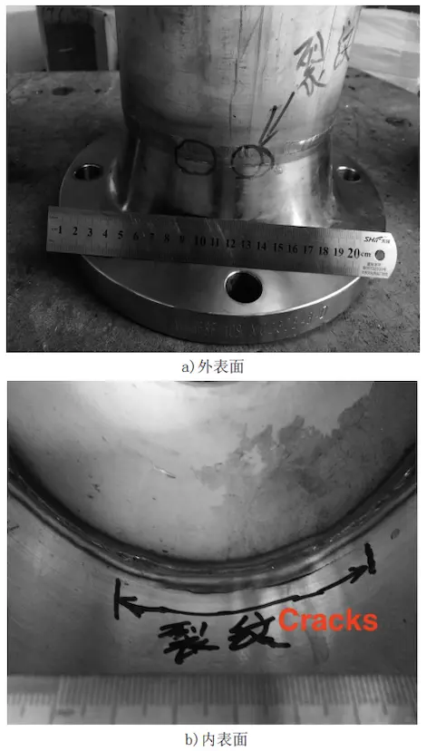
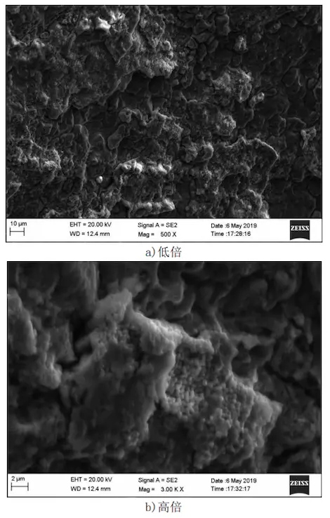
The macroscopic morphology of the high-neck flange was examined. Several cracks were found at the upper corner of the flange and near the weld joint. The cracks were distributed along the circumference of the flange. Obvious rust marks were present on the surface at the cracked area, as shown in Figure 1a. The stress at the cracked area is relatively concentrated, making crack initiation and propagation more likely. Additionally, Figure 1b shows that the crack extends through both the inner and outer surfaces of the entire high-neck flange and mainly propagates along the edge of the heat-affected zone of the weld joint. The heat-affected zone of the weld joint is relatively weak and exhibits high hardness. During welding, it is prone to excessive heating, leading to recrystallization and grain coarsening, which increases brittleness and results in cracking. The cracked section was broken to reveal the original, complete fracture surface. Following gasoline degreasing and ultrasonic cleaning with alcohol, the fracture micromorphology was examined using a field emission scanning electron microscope (SEM). The entire fracture surface was covered with oxides, as shown in Figure 2.
a) External surface b) Internal surface
Figure 1 Macroscopic morphology of cracked high-neck flange
a) Low magnification b) High magnification
Figure 2 SEM morphology of high-neck flange fracture

a) External surface b) Internal surface
Figure 1 Macroscopic morphology of cracked high-neck flange

a) Low magnification b) High magnification
Figure 2 SEM morphology of high-neck flange fracture
Wire cutting was used to obtain samples near the cracked area of the high-neck flange, and the chemical composition was analyzed using a spark direct-reading spectrometer. The results are presented in Table 1. It is evident that the content of each element meets the requirements of JIS G3214-1991 "Stainless Steel Forgings for Pressure Vessels" for SUS304 steel.
Table 1 Chemical Composition Analysis Results of High-Neck Flange (Mass Fraction %)
Table 1 Chemical Composition Analysis Results of High-Neck Flange (Mass Fraction %)
| Item | C | Si | Mn | P | S | Ni | Cr |
| Measured Value | 0.01 | 0.41 | 1.33 | 0.037 | 0.004 | 8.16 | 18.37 |
| Standard Value | ≤ 0.08 |
≤ 1.0 |
≤ 2.0 |
≤ 0.04 |
≤ 0.03 |
8.00-11.00 | 18.00-20.00 |
Mechanical property samples were prepared near the cracked position of the flange using a CNC lathe and a wire-cutting machine, and tensile property and Brinell hardness tests were performed using an electronic tensile testing machine and a Brinell hardness tester. The hardness test result is the average of three measurements. The test results are shown in Table 2. The table shows that the mechanical property parameters, including tensile strength, yield strength, elongation after fracture, cross-sectional shrinkage, and Brinell hardness values, all meet the technical requirements of JIS G3214-1991 "Stainless Steel Forgings for Pressure Vessels" for SUS304 steel.
Table 2 Test results of mechanical properties of high-neck flanges
Table 2 Test results of mechanical properties of high-neck flanges
| Item | Tensile Strength (MPa) | Yield Strength (MPa) | Elongation After Fracture (%) | Cross-Sectional Shrinkage (%) | Brinell Hardness (HBW5/750) |
| Actual Value | 679 | 306 | 60.5 | 78 | 164 |
| Standard Value | ≥520 | ≥205 | ≥43 | ≥50 | ≤187 |
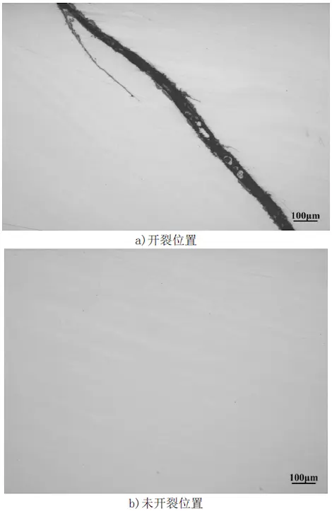
Wire cutting was used to take samples from the bag opening position and the unopened bag position, away from the bag pattern, for non-metallic inclusion detection and metallographic structure inspection. After grinding and polishing the two samples, no obvious inclusions such as sulfides, alumina, silicates, or spherical oxides were found under the metallographic microscope. According to the standard Method A of CB/T10561-2005 "Determination of Non-metallic Inclusions in Steel - Standard Rating Chart Microscopic Inspection Method," the inclusion levels were A0.5, A0.5e, B0.5, B0.5e, C0.5, C0.5e, D0.5, and D0.5e, as shown in Figure 3.
a) Crack position b) Uncracked position
Figure 3 Morphology of inclusions in high-neck flanges
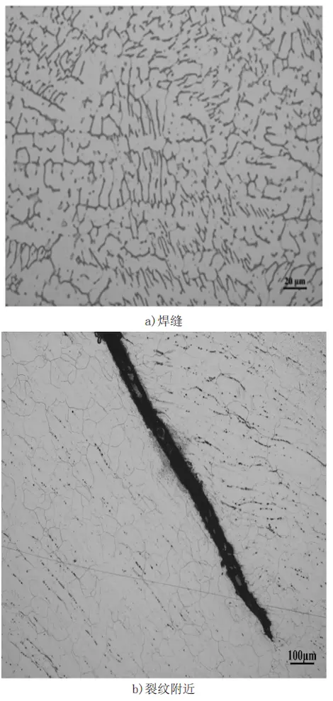
After grinding and polishing the two samples, followed by electrolytic corrosion with a 10% oxalic acid solution, their microstructure morphology was observed under a metallographic microscope. The observed area of the cracked sample includes the welding seam and the vicinity of the crack. The welding seam structure consists of austenite and dendritic ferrite, while the structure near the crack shows austenite with banded and dotted ferrite, as shown in Figure 4.
a) Welding seam b) Near the crack
Figure 4 Microstructure morphology of the cracked position of the high-neck flange
The microstructure at the uncracked position consists of austenite and banded, dotted ferrite, as shown in Figure 5. As seen in Figures 4 and 5, both the areas near the crack and the uncracked position consist of austenite and banded, dotted ferrite, with a relatively high ferrite content. A high ferrite content reduces the forgeability of austenitic stainless steel and increases the likelihood of cracking during material processing. It also decreases corrosion resistance and raises the risk of pitting corrosion. Additionally, ferrite can transform into brittle phases at high temperatures.
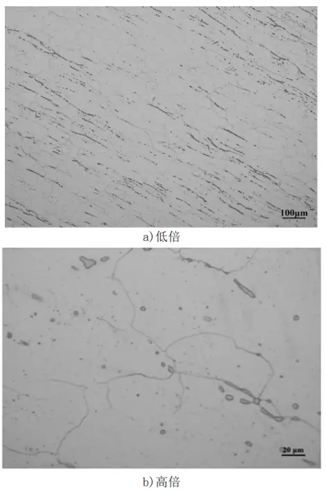
a) Low magnification b) High magnification
Figure 5 Microstructure morphology of the uncracked position of the high-neck flange

a) Crack position b) Uncracked position
Figure 3 Morphology of inclusions in high-neck flanges
After grinding and polishing the two samples, followed by electrolytic corrosion with a 10% oxalic acid solution, their microstructure morphology was observed under a metallographic microscope. The observed area of the cracked sample includes the welding seam and the vicinity of the crack. The welding seam structure consists of austenite and dendritic ferrite, while the structure near the crack shows austenite with banded and dotted ferrite, as shown in Figure 4.

a) Welding seam b) Near the crack
Figure 4 Microstructure morphology of the cracked position of the high-neck flange
The microstructure at the uncracked position consists of austenite and banded, dotted ferrite, as shown in Figure 5. As seen in Figures 4 and 5, both the areas near the crack and the uncracked position consist of austenite and banded, dotted ferrite, with a relatively high ferrite content. A high ferrite content reduces the forgeability of austenitic stainless steel and increases the likelihood of cracking during material processing. It also decreases corrosion resistance and raises the risk of pitting corrosion. Additionally, ferrite can transform into brittle phases at high temperatures.

a) Low magnification b) High magnification
Figure 5 Microstructure morphology of the uncracked position of the high-neck flange
The chemical composition and mechanical properties of the cracked stainless steel high-neck flange meet the technical requirements of the product standards for the raw material, such as tensile strength, yield strength, elongation after fracture, cross-sectional shrinkage, and Brinell hardness. No significant non-metallic inclusions, such as sulfides, alumina, silicates, or spherical oxides, were found in the high-neck flange, indicating a high purity of the raw materials.
The welding seam structure consists of austenite and dendritic ferrite, which forms a typical austenite-ferrite dual-phase structure. A welding seam with a dual-phase structure exhibits higher resistance to thermal cracking and intergranular corrosion compared to a single-phase austenite structure. The microstructures near both the cracked and uncracked areas consist of austenite, along with banded and dotted ferrite, with a high ferrite content. A high ferrite content negatively impacts the performance of austenitic stainless steel, damaging its forgeability and increasing the likelihood of crack formation during hot working. Additionally, it reduces the material's corrosion resistance and heightens the risk of pitting corrosion. In many corrosive environments, such as in urea production, the corrosion resistance deteriorates, and selective corrosion of ferrite may occur. When heated for extended periods at high temperatures, ferrite may transform into brittle phases, which embrittles the material and reduces its corrosion resistance.
The surface of the fracture at the crack location is severely oxidized, suggesting that the cracks may have formed before or during forging. The cracks are primarily located at the flange corners and near the heat-affected zone of the welded joint. Stress concentrates at the corners, making them more prone to cracking. The heat-affected zone is typically the weakest area of the welded joint. The uneven heat cycle during welding causes structural irregularities, leading to hardening and embrittlement, which in turn promotes the initiation and expansion of cracks.
In general, solution treatment and hot deformation processing reduce or eliminate the ferrite content in austenitic stainless steel. The primary method to reduce ferrite content is to increase the austenite-forming elements in the steel, with nickel being the preferred choice. However, from an economic perspective, nitrogen and manganese are gaining increasing attention. Nitrogen, in particular, has 30 times the resistance to ferrite formation compared to nickel. Additionally, it improves corrosion resistance and increases strength, making nitrogen-alloyed austenitic stainless steel increasingly popular.
The primary cause of the stainless steel high-neck flange cracking is the relatively high ferrite content in the raw material, which reduces the forgeability of the stainless steel and leads to cracks during forging. The stress concentration at the corner, along with the hardening and embrittlement caused by the uneven microstructure and properties of the heat-affected zone of the welded joint, further exacerbate the initiation and propagation of cracks, leading to failure after welding and installation.
Related News
- Installation of Main Bolts for Lap Joint Flange in High-Temperature Gas-Cooled Reactors
- Structural Design and Finite Element Analysis of Anchor Flanges
- Key Welding Technology for High-Neck Flange and Steel Pipe Joints
- The Design and Calculation of Stamped Lap Joint Flanges
- Development of Manufacturing Large Anchor Flanges
- Hardfacing the Inner Surface of Long-Neck Flanges Using CO₂ Gas-Shielded Welding
- UHV High-Neck Flange Welding
- Application of High-Neck Flange to UHV Steel Pipe Tower
- Analysis of the Cracking Cause of High-Neck Flanges
- Anchor Flanges for the East-West Gas Transmission Project
